


SECTION 5
TROUBLESHOOTING
27
10 SEC
PUSH
RELEASE
PUSH
RELEASE
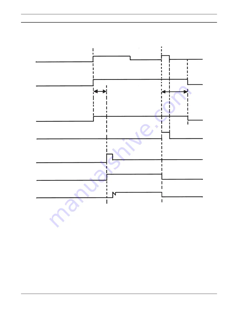
TORCH SWITCH
OPEN
CLOSE
GAS SOLENOID VALVE
POSTFLOW
CLOSE
OPEN
FLOW SWITCH
FAULT LIGHT
HF CIRCUIT
INVERTER
CUTTING ARC (CURRENT)
B.
TRIGGER LOCK "LOCK" position
ENERGIZE
NOTES:
1.
When the torch switch is pushed during postflow period, the postflow and preflow times are canceled, and the HF
is energized immediately.
2.
When the red fault light comes on, cutting operation should be stopped. The postflow time starts from the moment
the torch switch is released.
3.
FAULT light is on during second "turn-off" trigger only. This does not affect performance in any way.
PREFLOW
Postflow
2 SEC.
Summary of Contents for PCM-875
Page 29: ...28 D 36587 Figure 5 1 Schematic Diagram PCM 875 208 230 V 50 60 Hz 1 or 3 Phase ...
Page 30: ...29 D 36595 Figure 5 2 Wiring Diagram Sheet 1 of 2 PCM 875 208 230 V 50 60 Hz 1 or 3 Phase ...
Page 31: ...30 Figure 5 3 Wiring Diagram Sheet 2 of 2 PCM 875 208 230 V 50 60 Hz 1 or 3 Phase D 36595 ...
Page 32: ...31 D 36597 B Figure 5 4 Schematic Diagram PCM 875 400 460 V 50 60 Hz 3 Phase 1 2 3 4 5 6 ...
Page 33: ...32 D 36598 Figure 5 5 Wiring Diagram Sheet 1 of 2 PCM 875 400 460 V 50 60 Hz 3 Phase ...
Page 34: ...33 D 36598 Figure 5 6 Wiring Diagram Sheet 2 of 2 PCM 875 400 460 V 50 60 Hz 3 Phase ...
Page 35: ...34 D 36715 A Figure 5 7 Schematic Diagram PCM 875 575 V 60 Hz 3 Phase ...
Page 36: ...35 D 36716 Figure 5 8 Wiring Diagram Sheet 1 of 2 PCM 875 575 V 60 Hz 3 Phase ...
Page 37: ...36 D 36716 Figure 5 9 Wiring Diagram Sheet 2 of 2 PCM 875 575 V 60 Hz 3 Phase ...
Page 47: ...46 ...


