30
SEKTION 4
BETJENING
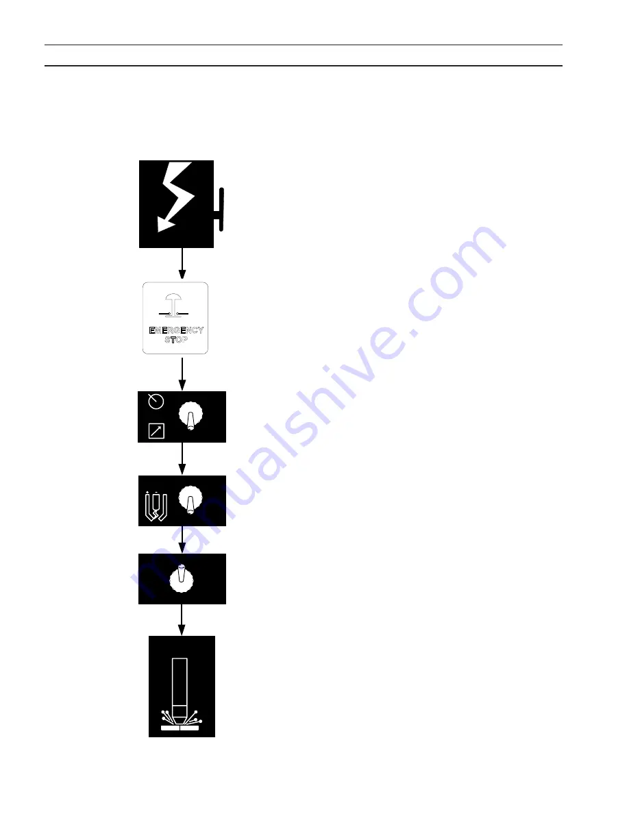
1. Tænd for strømmen på netafbryderkontakten (væg). (EPP-450
har ikke en tænd/sluk (on/off) vælgerkontakt). Lampen for
hovedstrøm vil lyse, og fejllampen vil blinke og herefter slukke.
2. Nødstopknappen trækkes ud.
3. Vælg indstillingen for panel/fjernstyring.
4. Indstilling af pilotlysbue høj/lav vælgerkontakt. Hvis der
vælges pilotlysbue høj/lav fra en fjernstyring, skal kontakten
være i position Low (lav). (Der henvises til skæredata i bræn-
derens instruktionsbog).
5. Hvis man bruger panelarbejdsmåde, så kan man få vist de
forudindstillede Amp ved hjælp af vælgerkontakten ACTUAL /
PRESET AMPS. Justér strømmen, indtil den omtrentlige øn-
skede værdi vises på amperemeteret. Hvis man bruger fjern-
styringsmåde, kræver det, at man fjernstyrer den oprindelige
udgangsstrøm, når man placerer de faktiske kontakter Amp/
forudindstillet Amp i positionen forudindstillet Amp.
6. Begynd på plasmaskæringen. Dette omfatter muligvis manuel
indstilling af andre valgmuligheder, afhængig af den totale
plasmapakke.
7. Hvis man bruger panelarbejdsmåden, efter at man er be-
gyndt at skære, skal man justere strømmen til den ønskede
mængde.
8. Kontrollér, om fejllamper tændes, hvis skæring eller markering
ikke kan påbegyndes. Hvis en fejllampe tændes, så henvises
man til afsnittet Fejlfinding.
Bemærk:
Fejllampen blinker, når kontaktoren tændes for før-
ste gang, hvilket betyder, at der er tændt for jævn-
strøms-bus på normal vis.
4.3 Betjeningsrækkefølge
SECTION 4 Operation
ESP 400C Plasma Power Source
ESP 400C Plasma Power Source
ESP 400C Plasma Power Source
ESP 400C Plasma Power Source
4-4
Begin
Cutting
ACTUAL AMPS
PRESET AMPS
HIGH
LOW
PILOT
ARC
PANEL
REMOTE
Apply Power
4.3 Sequence of Operation
1.
Apply power by closing the line (wall) switch.
(The ESP-400C does not have an on/off
switch). The main power light will illuminate
and the fault light will flash and then go out.
2.
Select the Panel/Remote setting.
3.
Set pilot arc High/Low switch. (Refer to cutting
data in the torch manual.)
4.
If using panel mode, view preset amps with the
ACTUAL/PRESET AMPS switch. Adjust current
until the approximate desired value is shown on
the ammeter.
5.
Begin plasma cutting operation. This may
include manually setting up other options,
depending on the total plasma package.
6.
If using panel mode, after cutting has begun,
adjust current to desired amount.
7.
Check for fault light. If a fault light illuminates,
refer to troubleshooting section.
Note: The fault light flashes when the contactor is
Note: The fault light flashes when the contactor is
Note: The fault light flashes when the contactor is
Note: The fault light flashes when the contactor is
first turned on signifying the DC Bus powered up
first turned on signifying the DC Bus powered up
first turned on signifying the DC Bus powered up
first turned on signifying the DC Bus powered up
normally.
normally.
normally.
normally.
4.4 Arc Initiation Settings
The time to achieve full current can be adjusted to
suit your particular system. This feature uses 50%
of the cutting current to start, dwell and then
gradually (less than a second) achieve full current.
The ESP-400C is factory shipped with this feature
enabled. The default settings are:
Minimum Start Current
40A
Start Current
50% of cut current
Timing to achieve full current
800 msec
Dwell Time
50 msec
Summary of Contents for Plasmarc EPP-450
Page 1: ...0558007944 08 2014 Plasmastrømkilde Instruktionsbog DA EPP 450 ...
Page 3: ......
Page 4: ...4 ...
Page 63: ...63 section 6 TROUBLESHOOTING ...
Page 65: ...65 notes ...
Page 66: ...66 notes ...


