

10
167
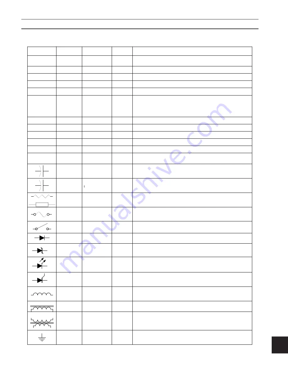
GROUND
T n
L n
L n
SILICON
D n
D n
D n
SW n
F n
ELECTROLITIC
RESISTOR
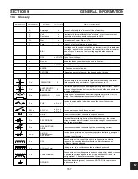
DESCRIPTION
Wound wire device; current through the coil generates a electro-
magnetic field causing inductive reactance, which increases with
number of turns and density.
Adding a core to a coil increases the inductance produced.
Wound wire device with a primary and secondary coil(s) which increases
or decreases voltage applied to the primary based on coil and core
configuration. 1:1 transformers are used for isolation.
Identifies the earth (ground) connection. NOTE: Not for a protective
earth connection.
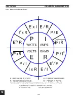
OCV
Amperage
Volts
Resistance
A measure of Power. Watts = V*A
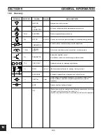
+ Positive element of device.
- Negative element of device - the banded end of a diode.
Device which opens and closes a circuit.
A semi-conductor that conducts in only one direction
Semiconductor diode that emits light when conducting current
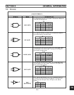
Device having primary and secondary inductors for altering a-c signal
amplitudes, impedance matching,and isolation purposes. . A reverse
blocking triode thyristor
A diode that permits high current flow without damage, the reverse
voltage remains almost constant over a wide range of currents, used
esp. to regulate voltage.
Device in series with a load which opens the circuit if its current
rating (A) is exceeded.
Component that opposes current flow proportionately to its Ohm (
)
rating. Power dissapation is expressed in Watts (
).
Electrolitic capacitors will be damaged if polarity is not correct. Capaci-
tors can charge themselves from ambient electric fields and should be
handled with caution.
Stores energy in the electrostatic field generated between two metal
plates separated by an insulator. Typical values are in F.
SYMBOL
n
A
V
R
W
BIAS
ANODE:
CATHODE:
+
-
C n
+
A voltage used to control or stabilize an electronic circuit. A forward bias
is voltage applied in the direction of the current flow within a transistor,
tube or circuit. A reverse bias is voltage applied in the opposite
direction.
Watt
n
n
n
n
n VOLTS
Number
micro
0.00000n
Open Circuit Voltage:
Indicates that any number may be used in its place.
One Millionth of any unit.
F
Farad
n
Amount of electrical storage in a capacitor.
C n
CAPACITOR
F
CAPACITOR
F
R n
, W
Opposition to electron transfer: expressed in OHMS.
FUSE
n A, n V
Current: effectively the "amount of flow" of electricity.
Electromotive force: effectively the "pressure" of electron movement.
SWITCH
n A, n V
n P, n T
DIODE
ZENER DIODE
LIGHT EMITTING
DIODE
RECTIFIER
CONTROLLED
SCR
COIL
COIL (Iron Core)
TRANSFORMER
NOTATION
NAME
VALUES
-
+
or
10.4 Glossary
SECTION 9
gENERAl INfORMATION
Summary of Contents for PowerCut 1600
Page 16: ...3 0 16 section 3 SPECIFICATIONS 3 4 Machine Operation Flowchart...
Page 27: ...4 2 27 4 2 Control Transformer T2 0558007188 SECTION 4 DESCRIPTION OF OPERATION...
Page 30: ...4 3 30 4 3 Input Bridge 0558007068 0558007077 SECTION 4 DESCRIPTION OF OPERATION...
Page 35: ...4 6 35 blank...
Page 38: ...4 8 38 4 8 PCB1 Control Board 0558038317 SECTION 4 DESCRIPTION OF OPERATION 4 10 6 8 5 3 11 7...
Page 52: ...4 8 52 4 8 14 PCB1 Layout 0558038317 SECTION 4 DESCRIPTION OF OPERATION...
Page 60: ...4 10 60 4 10 2 Power PC Board Schematic 2 0558038315 SECTION 4 DESCRIPTION OF OPERATION 3 14 8...
Page 67: ...4 10 67 4 10 7 Power Board_PCB2 Control Relays 0558038315 SECTION 4 DESCRIPTION OF OPERATION...
Page 77: ...4 10 77 4 10 16 Buss Supply IGBT SECTION 4 DESCRIPTION OF OPERATION...
Page 91: ...4 11 91 4 11 Power Driver 0558038335 SECTION 4 DESCRIPTION OF OPERATION...
Page 109: ...4 19 109 SECTION 4 DESCRIPTION OF OPERATION 4 19 PT38 Plasma Torch...
Page 110: ...4 19 110 SECTION 4 DESCRIPTION OF OPERATION 4 19 PT38 Plasma Torch...
Page 113: ...5 0 113 5 1 Wiring Diagram 230 460 Volt 0558007543 section 5 WIring diagrams...
Page 114: ...5 0 114 5 1 Wiring Diagram 230 460 Volt 0558007543 section 5 WIring diagrams...
Page 115: ...5 0 115 5 1 Wiring Diagram 230 460 Volt 0558007543 section 5 WIring diagrams...
Page 116: ...5 0 116 section 5 WIring diagrams 5 1 Wiring Diagram 230 460 Volt 0558007543...
Page 117: ...5 0 117 section 5 WIring diagrams 5 1 Wiring Diagram 230 460 Volt 0558007543...
Page 118: ...5 0 118 5 2 Wiring Diagram 400 400V CE 0558007547 section 5 WIring diagrams...
Page 119: ...5 0 119 section 5 WIring diagrams 5 2 Wiring Diagram 400 400V CE 0558007547...
Page 120: ...5 0 120 5 2 Wiring Diagram 400 400V CE 0558007547 section 5 WIring diagrams...
Page 121: ...5 0 121 section 5 WIring diagrams 5 2 Wiring Diagram 400 400V CE 0558007547...
Page 122: ...5 0 122 5 2 Wiring Diagram 400 400V CE 0558007547 section 5 WIring diagrams...
Page 123: ...5 0 123 section 5 WIring diagrams 5 2 Wiring Diagram 400 400V CE 0558007547...
Page 124: ...124 5 3 Wiring Diagram 575V 0558007545 section 5 WIring diagrams...
Page 125: ...125 section 5 WIring diagrams 5 3 Wiring Diagram 575V 0558007545...
Page 126: ...126 5 3 Wiring Diagram 575V 0558007545 section 5 WIring diagrams...
Page 127: ...127 section 5 WIring diagrams 5 3 Wiring Diagram 575V 0558007545...
Page 128: ...128 5 3 Wiring Diagram 575V 0558007545 section 5 WIring diagrams...
Page 129: ...129 section 5 WIring diagrams 5 3 Wiring Diagram 575V 0558007545...
Page 130: ...130 blank...
Page 135: ...6 0 blank 135...
Page 136: ...6 0 136 section 6 replacement parts 6 3 Front 0558007540...
Page 140: ...6 0 140 6 3 Top 0558007540 section 6 replacement parts...
Page 144: ...6 0 144 section 6 replacement parts 6 3 Left Inside2 0558007540...
Page 146: ...6 0 146 section 6 replacement parts 6 3 Rear View 0558007540...
Page 148: ...6 0 148 6 3 Front Rear Isometric Views 0558007540 section 6 replacement parts...
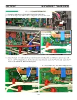
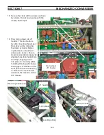
Page 159: ...159 section 7 mechanized conversion 20 Trim all tie wraps and replace the unit s cover...
Page 166: ...10 166 SECTION 9 General information 10 3 Ohm s and Watt s Laws...
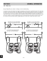
Page 171: ...10 171 10 6 Ohm Testing SECTION 9 General information...
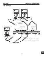
Page 172: ...10 172 10 7 Diode Testing SECTION 9 General information...
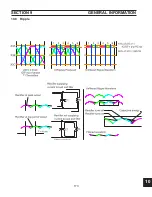
Page 173: ...10 173 10 8 Ripple SECTION 9 General information...
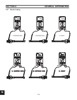
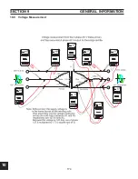
Page 174: ...10 174 10 9 Voltage Measurement SECTION 9 General information...
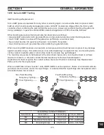
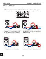
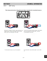
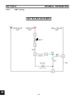
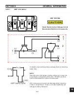
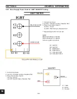
Page 178: ...10 178 IGBT Tester Schematic 10 10 1 IGBT Testing SECTION 8 General information...
Page 182: ...182 revision history Original release 11 2008 1...


