
10
168
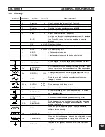
PLUG
CONNECTION
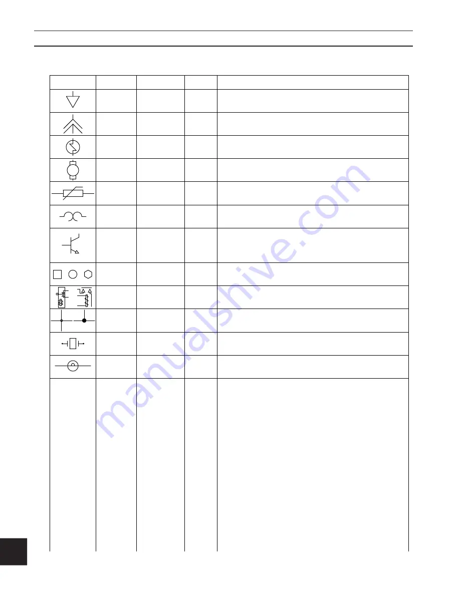
Variously configured male/female separable connectors.
DESCRIPTION
SYMBOL NOTATION
NAME
VALUES
SOL n
SOLENOID
Electro-magnetically operated valve.
M n
MOTOR
n Ø,HP,V
THERMAL
T SW n
Protective device that protects circuits from over temperature.
SWITCH
Q n
TRANSISTOR
THERMISTOR
TEST POINT
TP n
Dedicated location for obtaining quantification.
RELAY
K n
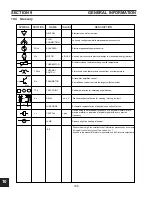
Produces light by heating a filament.
WIRE NODE
Schematic representation of physical connection of wires.
n MHz
Y n
CRYSTAL
Device using the mechanical resonance of a physical crystal of piezo-
electric material to create an electrical signal with a very precise
frequency.
A device which converts electrical energy to mechanical energy (motion).
n A, n V
LAMP
NEUTRAL
Electronic neutral or common.
Electro-mechanical device for opening / closing a circuit.
BIT
Short for binary digit, the smallest unit of information processed by a computer.
A single bit can hold only one of two values: 0 or 1.
As used in this manual BitI refers to input data, and BitO refers to output data.
Mn
or
n
n
n
n
n
or
A resistor whose resistance changes with temperature.
or
A transistor amplifies current.
A small base current controls the larger collector current.
Base
Emitter
Collector
ltr
or
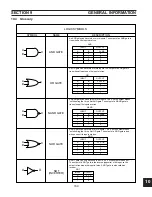
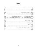
10.4 Glossary
SECTION 9
gENERAl INfORMATION
Summary of Contents for PowerCut 1600
Page 16: ...3 0 16 section 3 SPECIFICATIONS 3 4 Machine Operation Flowchart...
Page 27: ...4 2 27 4 2 Control Transformer T2 0558007188 SECTION 4 DESCRIPTION OF OPERATION...
Page 30: ...4 3 30 4 3 Input Bridge 0558007068 0558007077 SECTION 4 DESCRIPTION OF OPERATION...
Page 35: ...4 6 35 blank...
Page 38: ...4 8 38 4 8 PCB1 Control Board 0558038317 SECTION 4 DESCRIPTION OF OPERATION 4 10 6 8 5 3 11 7...
Page 52: ...4 8 52 4 8 14 PCB1 Layout 0558038317 SECTION 4 DESCRIPTION OF OPERATION...
Page 60: ...4 10 60 4 10 2 Power PC Board Schematic 2 0558038315 SECTION 4 DESCRIPTION OF OPERATION 3 14 8...
Page 67: ...4 10 67 4 10 7 Power Board_PCB2 Control Relays 0558038315 SECTION 4 DESCRIPTION OF OPERATION...
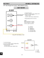
Page 77: ...4 10 77 4 10 16 Buss Supply IGBT SECTION 4 DESCRIPTION OF OPERATION...
Page 91: ...4 11 91 4 11 Power Driver 0558038335 SECTION 4 DESCRIPTION OF OPERATION...
Page 109: ...4 19 109 SECTION 4 DESCRIPTION OF OPERATION 4 19 PT38 Plasma Torch...
Page 110: ...4 19 110 SECTION 4 DESCRIPTION OF OPERATION 4 19 PT38 Plasma Torch...
Page 113: ...5 0 113 5 1 Wiring Diagram 230 460 Volt 0558007543 section 5 WIring diagrams...
Page 114: ...5 0 114 5 1 Wiring Diagram 230 460 Volt 0558007543 section 5 WIring diagrams...
Page 115: ...5 0 115 5 1 Wiring Diagram 230 460 Volt 0558007543 section 5 WIring diagrams...
Page 116: ...5 0 116 section 5 WIring diagrams 5 1 Wiring Diagram 230 460 Volt 0558007543...
Page 117: ...5 0 117 section 5 WIring diagrams 5 1 Wiring Diagram 230 460 Volt 0558007543...
Page 118: ...5 0 118 5 2 Wiring Diagram 400 400V CE 0558007547 section 5 WIring diagrams...
Page 119: ...5 0 119 section 5 WIring diagrams 5 2 Wiring Diagram 400 400V CE 0558007547...
Page 120: ...5 0 120 5 2 Wiring Diagram 400 400V CE 0558007547 section 5 WIring diagrams...
Page 121: ...5 0 121 section 5 WIring diagrams 5 2 Wiring Diagram 400 400V CE 0558007547...
Page 122: ...5 0 122 5 2 Wiring Diagram 400 400V CE 0558007547 section 5 WIring diagrams...
Page 123: ...5 0 123 section 5 WIring diagrams 5 2 Wiring Diagram 400 400V CE 0558007547...
Page 124: ...124 5 3 Wiring Diagram 575V 0558007545 section 5 WIring diagrams...
Page 125: ...125 section 5 WIring diagrams 5 3 Wiring Diagram 575V 0558007545...
Page 126: ...126 5 3 Wiring Diagram 575V 0558007545 section 5 WIring diagrams...
Page 127: ...127 section 5 WIring diagrams 5 3 Wiring Diagram 575V 0558007545...
Page 128: ...128 5 3 Wiring Diagram 575V 0558007545 section 5 WIring diagrams...
Page 129: ...129 section 5 WIring diagrams 5 3 Wiring Diagram 575V 0558007545...
Page 130: ...130 blank...
Page 135: ...6 0 blank 135...
Page 136: ...6 0 136 section 6 replacement parts 6 3 Front 0558007540...
Page 140: ...6 0 140 6 3 Top 0558007540 section 6 replacement parts...
Page 144: ...6 0 144 section 6 replacement parts 6 3 Left Inside2 0558007540...
Page 146: ...6 0 146 section 6 replacement parts 6 3 Rear View 0558007540...
Page 148: ...6 0 148 6 3 Front Rear Isometric Views 0558007540 section 6 replacement parts...
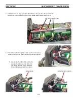
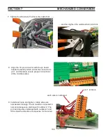
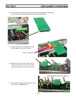
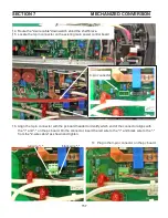
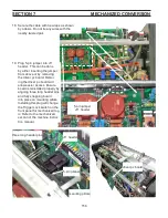
Page 159: ...159 section 7 mechanized conversion 20 Trim all tie wraps and replace the unit s cover...
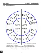
Page 166: ...10 166 SECTION 9 General information 10 3 Ohm s and Watt s Laws...
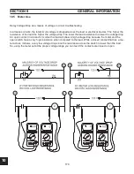
Page 171: ...10 171 10 6 Ohm Testing SECTION 9 General information...
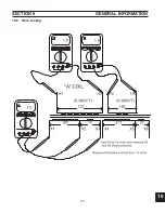
Page 172: ...10 172 10 7 Diode Testing SECTION 9 General information...
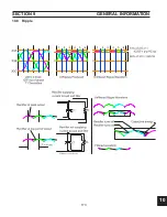
Page 173: ...10 173 10 8 Ripple SECTION 9 General information...
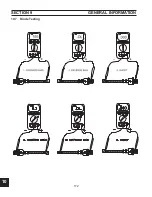
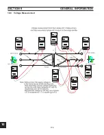
Page 174: ...10 174 10 9 Voltage Measurement SECTION 9 General information...
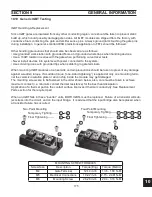
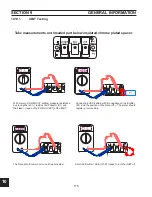
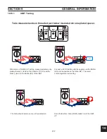
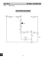
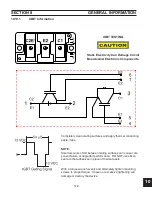
Page 178: ...10 178 IGBT Tester Schematic 10 10 1 IGBT Testing SECTION 8 General information...
Page 182: ...182 revision history Original release 11 2008 1...


