10
175
IGBT Handling & Replacement
Since IGBT gates are insulated from any other conducting region, care should be taken to prevent static
build up, which could possibly damage gate oxides. All IGBT modules are shipped from the factory with
conductive foam contacting the gate and emitter sense pins. Always ground parts touching the gate pins
during installation. In general, standard ESD predictions application to FETs should be followed.
Other handling precautions that should also be observed are as follows:
• Use grounded work station with grounded floors and grounded wrist straps when handling devices.
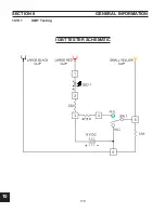
• Use a 100W resistor in series with the gate when performing curve tracer tests.
• Never install devices into systems with power connected to the system.
• Use soldering irons with grounded tips when soldering to gate terminals.
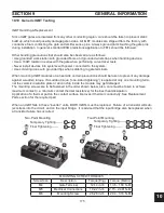
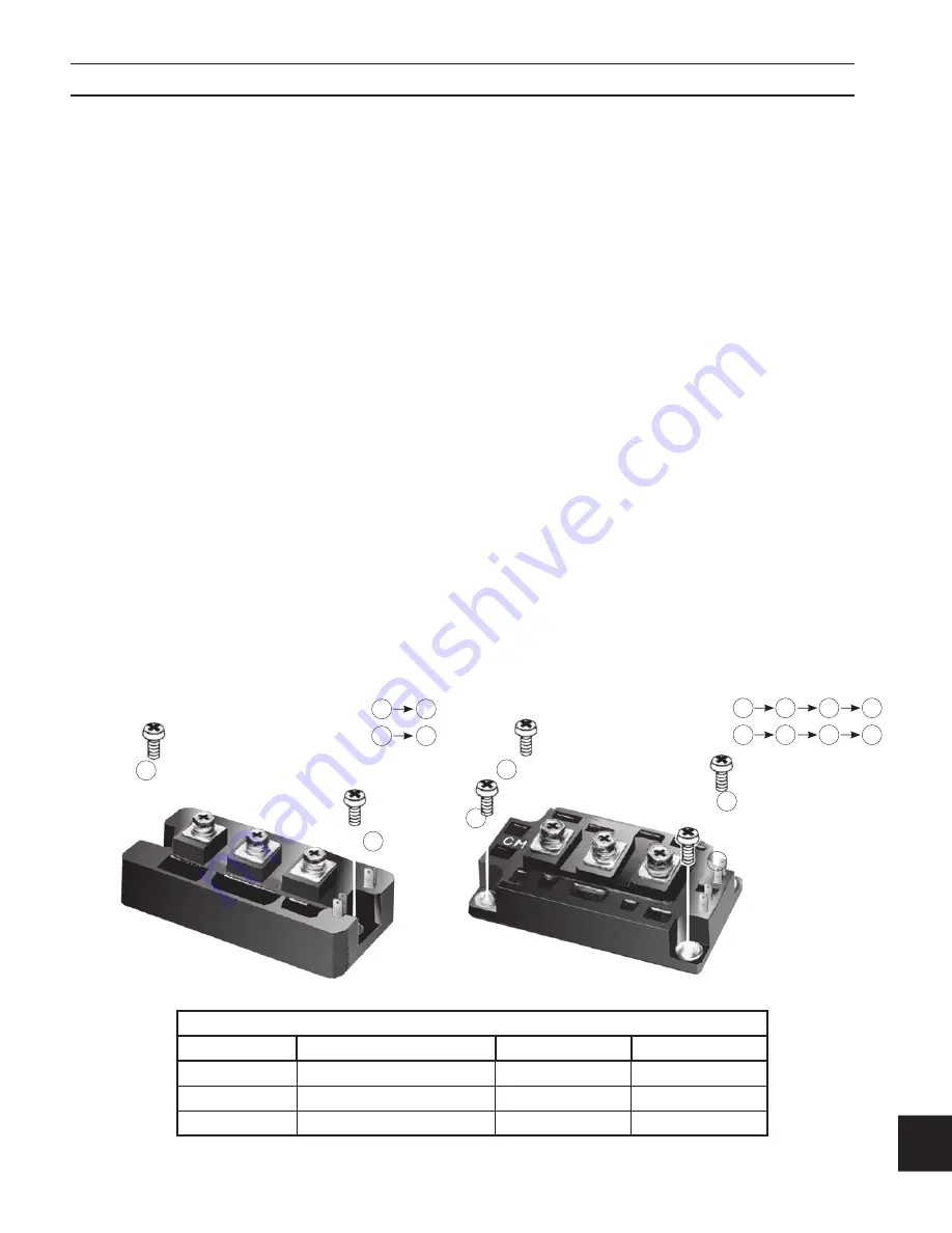
When mounting IGBT modules on a heatsink, certain precautions should be taken to prevent any damage
against a sudden torque. If a sudden torque (“one-sided tightening”) is applied at only one mounting termi-
nal the ceramic insulation plate or silicon chip inside the module may get damaged.
The mounting screws are to be fastened in the order shown below, also, care must be taken to achieve
maximum contact (i.e. minimum contact thermal resistance) for the best heat dissipation.
Application of a thermal pad on the contact surface improves it thermal conductivity. See Replacement
Parts section for the required pad.
When an IGBT fails in these “inverter” units, BOTH IGBTs must be replaced. Failure of a transistor will sub-
ject stress into the circuit, and on the input bridge. It is advised that the input bridge also be replaced when
a transistor failure has occurred.
MOUNTING SCREW TORQUES
Screw Size
Description
Torque (Eng)
Torque (Metric)
M4
Gate Terminal
12-14 in-lb
1.36 - 1.58 N-M
M5
Electrical Connections
19-22 in-lb
2.15 - 2.481 N-M
M6
Mounting Screw
26-28 in-lb
2.94 - 3.16 N-M
10.10
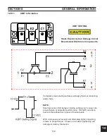
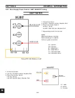
Generic IGBT Testing
2
4
3
1
2
4
3
1
2
4
3
1
2
1
2
Two-Point Mounting
Four-Point Mounting
Temporary Tighting ------
Final Tightening ------
Temporary Tighting ------
Final Tightening ------
1
2
1
SECTION 9
gENERAl INfORMATION
Summary of Contents for PowerCut 1600
Page 16: ...3 0 16 section 3 SPECIFICATIONS 3 4 Machine Operation Flowchart...
Page 27: ...4 2 27 4 2 Control Transformer T2 0558007188 SECTION 4 DESCRIPTION OF OPERATION...
Page 30: ...4 3 30 4 3 Input Bridge 0558007068 0558007077 SECTION 4 DESCRIPTION OF OPERATION...
Page 35: ...4 6 35 blank...
Page 38: ...4 8 38 4 8 PCB1 Control Board 0558038317 SECTION 4 DESCRIPTION OF OPERATION 4 10 6 8 5 3 11 7...
Page 52: ...4 8 52 4 8 14 PCB1 Layout 0558038317 SECTION 4 DESCRIPTION OF OPERATION...
Page 60: ...4 10 60 4 10 2 Power PC Board Schematic 2 0558038315 SECTION 4 DESCRIPTION OF OPERATION 3 14 8...
Page 67: ...4 10 67 4 10 7 Power Board_PCB2 Control Relays 0558038315 SECTION 4 DESCRIPTION OF OPERATION...
Page 77: ...4 10 77 4 10 16 Buss Supply IGBT SECTION 4 DESCRIPTION OF OPERATION...
Page 91: ...4 11 91 4 11 Power Driver 0558038335 SECTION 4 DESCRIPTION OF OPERATION...
Page 109: ...4 19 109 SECTION 4 DESCRIPTION OF OPERATION 4 19 PT38 Plasma Torch...
Page 110: ...4 19 110 SECTION 4 DESCRIPTION OF OPERATION 4 19 PT38 Plasma Torch...
Page 113: ...5 0 113 5 1 Wiring Diagram 230 460 Volt 0558007543 section 5 WIring diagrams...
Page 114: ...5 0 114 5 1 Wiring Diagram 230 460 Volt 0558007543 section 5 WIring diagrams...
Page 115: ...5 0 115 5 1 Wiring Diagram 230 460 Volt 0558007543 section 5 WIring diagrams...
Page 116: ...5 0 116 section 5 WIring diagrams 5 1 Wiring Diagram 230 460 Volt 0558007543...
Page 117: ...5 0 117 section 5 WIring diagrams 5 1 Wiring Diagram 230 460 Volt 0558007543...
Page 118: ...5 0 118 5 2 Wiring Diagram 400 400V CE 0558007547 section 5 WIring diagrams...
Page 119: ...5 0 119 section 5 WIring diagrams 5 2 Wiring Diagram 400 400V CE 0558007547...
Page 120: ...5 0 120 5 2 Wiring Diagram 400 400V CE 0558007547 section 5 WIring diagrams...
Page 121: ...5 0 121 section 5 WIring diagrams 5 2 Wiring Diagram 400 400V CE 0558007547...
Page 122: ...5 0 122 5 2 Wiring Diagram 400 400V CE 0558007547 section 5 WIring diagrams...
Page 123: ...5 0 123 section 5 WIring diagrams 5 2 Wiring Diagram 400 400V CE 0558007547...
Page 124: ...124 5 3 Wiring Diagram 575V 0558007545 section 5 WIring diagrams...
Page 125: ...125 section 5 WIring diagrams 5 3 Wiring Diagram 575V 0558007545...
Page 126: ...126 5 3 Wiring Diagram 575V 0558007545 section 5 WIring diagrams...
Page 127: ...127 section 5 WIring diagrams 5 3 Wiring Diagram 575V 0558007545...
Page 128: ...128 5 3 Wiring Diagram 575V 0558007545 section 5 WIring diagrams...
Page 129: ...129 section 5 WIring diagrams 5 3 Wiring Diagram 575V 0558007545...
Page 130: ...130 blank...
Page 135: ...6 0 blank 135...
Page 136: ...6 0 136 section 6 replacement parts 6 3 Front 0558007540...
Page 140: ...6 0 140 6 3 Top 0558007540 section 6 replacement parts...
Page 144: ...6 0 144 section 6 replacement parts 6 3 Left Inside2 0558007540...
Page 146: ...6 0 146 section 6 replacement parts 6 3 Rear View 0558007540...
Page 148: ...6 0 148 6 3 Front Rear Isometric Views 0558007540 section 6 replacement parts...
Page 159: ...159 section 7 mechanized conversion 20 Trim all tie wraps and replace the unit s cover...
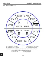
Page 166: ...10 166 SECTION 9 General information 10 3 Ohm s and Watt s Laws...
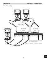
Page 171: ...10 171 10 6 Ohm Testing SECTION 9 General information...
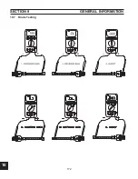
Page 172: ...10 172 10 7 Diode Testing SECTION 9 General information...
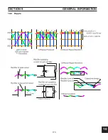
Page 173: ...10 173 10 8 Ripple SECTION 9 General information...
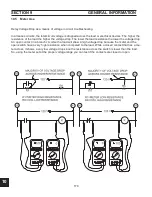
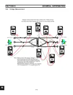
Page 174: ...10 174 10 9 Voltage Measurement SECTION 9 General information...
Page 178: ...10 178 IGBT Tester Schematic 10 10 1 IGBT Testing SECTION 8 General information...
Page 182: ...182 revision history Original release 11 2008 1...

