
4.8
51
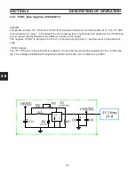
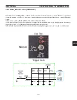
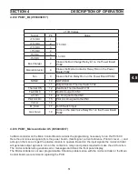
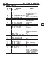
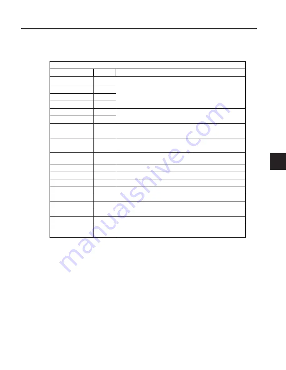
J1 I/O Values
Signal
Pin
Value
+15 VDC
1
+15 VDC
+15 VDC
2
+15 VDC
3
+15 VDC
4
-15 VDC
5
-15 VDC
-15 VDC
6
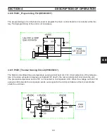
Bus Charger
7
Closes the Bus Charger Relay K1 on the Power Board
PCB2
MainsContactor
8
Closes the Mains Contactor Relay RL3 on the Power
Board PCB2
Fan
9
Closes the Fan Relay RL2 on the Power Board PCB2
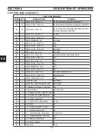
NONE
10
NOT USED
11
Output Inductor Thermal Switch TS2
Thermal HS
12
Heat Sink Thermal Switch TS1
Fault Bit 0
13
Fault bit output to CNC
Arc On
14
Arc On signal to the CNC
Pilot Arc On
15
Pilot Arc On signal to the CNC
Corner
16
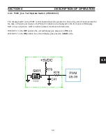
M_Start
17
Torch Switch input
Gas Valve
18
Turns on the Gas Valve Relay RL1 on the Power Board
PCB2
SECTION 4
DESCRIPTION Of OPERATION
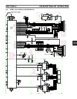
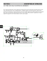
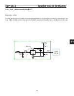
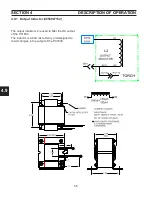
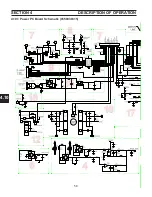
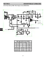
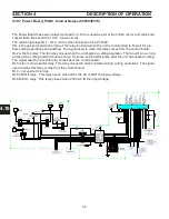
he Microcontroller on the Main Control Board contains the programming necessary to run the PC1600.
Here the unit receives signals from the power board– (Start signal, current reference, Pilot Arc level …) and
acts upon them so as to get the plasma console to operate. Based on the input signals the microcontroller
will generate output signals to turn on the contactors, relays and pulses required to make the unit function.
The microcontroller also generates error messages and drives the front panel display.
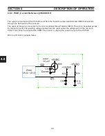
The Microcontroller is not user programmable. Should a problem arise with the microcontroller or the Main
Control board, we recommend replacing the PCB.
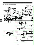
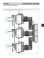
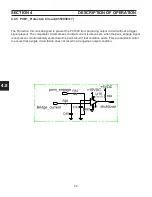
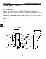
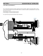
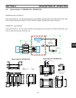
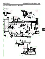
4.8.12 PCb1_I/O (0558038317)
4.8.13 PCb1_Microcontroller u5 (0558038317)
Summary of Contents for PowerCut 1600
Page 16: ...3 0 16 section 3 SPECIFICATIONS 3 4 Machine Operation Flowchart...
Page 27: ...4 2 27 4 2 Control Transformer T2 0558007188 SECTION 4 DESCRIPTION OF OPERATION...
Page 30: ...4 3 30 4 3 Input Bridge 0558007068 0558007077 SECTION 4 DESCRIPTION OF OPERATION...
Page 35: ...4 6 35 blank...
Page 38: ...4 8 38 4 8 PCB1 Control Board 0558038317 SECTION 4 DESCRIPTION OF OPERATION 4 10 6 8 5 3 11 7...
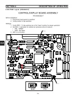
Page 52: ...4 8 52 4 8 14 PCB1 Layout 0558038317 SECTION 4 DESCRIPTION OF OPERATION...
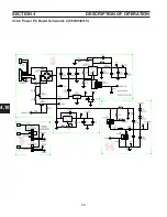
Page 60: ...4 10 60 4 10 2 Power PC Board Schematic 2 0558038315 SECTION 4 DESCRIPTION OF OPERATION 3 14 8...
Page 67: ...4 10 67 4 10 7 Power Board_PCB2 Control Relays 0558038315 SECTION 4 DESCRIPTION OF OPERATION...
Page 77: ...4 10 77 4 10 16 Buss Supply IGBT SECTION 4 DESCRIPTION OF OPERATION...
Page 91: ...4 11 91 4 11 Power Driver 0558038335 SECTION 4 DESCRIPTION OF OPERATION...
Page 109: ...4 19 109 SECTION 4 DESCRIPTION OF OPERATION 4 19 PT38 Plasma Torch...
Page 110: ...4 19 110 SECTION 4 DESCRIPTION OF OPERATION 4 19 PT38 Plasma Torch...
Page 113: ...5 0 113 5 1 Wiring Diagram 230 460 Volt 0558007543 section 5 WIring diagrams...
Page 114: ...5 0 114 5 1 Wiring Diagram 230 460 Volt 0558007543 section 5 WIring diagrams...
Page 115: ...5 0 115 5 1 Wiring Diagram 230 460 Volt 0558007543 section 5 WIring diagrams...
Page 116: ...5 0 116 section 5 WIring diagrams 5 1 Wiring Diagram 230 460 Volt 0558007543...
Page 117: ...5 0 117 section 5 WIring diagrams 5 1 Wiring Diagram 230 460 Volt 0558007543...
Page 118: ...5 0 118 5 2 Wiring Diagram 400 400V CE 0558007547 section 5 WIring diagrams...
Page 119: ...5 0 119 section 5 WIring diagrams 5 2 Wiring Diagram 400 400V CE 0558007547...
Page 120: ...5 0 120 5 2 Wiring Diagram 400 400V CE 0558007547 section 5 WIring diagrams...
Page 121: ...5 0 121 section 5 WIring diagrams 5 2 Wiring Diagram 400 400V CE 0558007547...
Page 122: ...5 0 122 5 2 Wiring Diagram 400 400V CE 0558007547 section 5 WIring diagrams...
Page 123: ...5 0 123 section 5 WIring diagrams 5 2 Wiring Diagram 400 400V CE 0558007547...
Page 124: ...124 5 3 Wiring Diagram 575V 0558007545 section 5 WIring diagrams...
Page 125: ...125 section 5 WIring diagrams 5 3 Wiring Diagram 575V 0558007545...
Page 126: ...126 5 3 Wiring Diagram 575V 0558007545 section 5 WIring diagrams...
Page 127: ...127 section 5 WIring diagrams 5 3 Wiring Diagram 575V 0558007545...
Page 128: ...128 5 3 Wiring Diagram 575V 0558007545 section 5 WIring diagrams...
Page 129: ...129 section 5 WIring diagrams 5 3 Wiring Diagram 575V 0558007545...
Page 130: ...130 blank...
Page 135: ...6 0 blank 135...
Page 136: ...6 0 136 section 6 replacement parts 6 3 Front 0558007540...
Page 140: ...6 0 140 6 3 Top 0558007540 section 6 replacement parts...
Page 144: ...6 0 144 section 6 replacement parts 6 3 Left Inside2 0558007540...
Page 146: ...6 0 146 section 6 replacement parts 6 3 Rear View 0558007540...
Page 148: ...6 0 148 6 3 Front Rear Isometric Views 0558007540 section 6 replacement parts...
Page 159: ...159 section 7 mechanized conversion 20 Trim all tie wraps and replace the unit s cover...
Page 166: ...10 166 SECTION 9 General information 10 3 Ohm s and Watt s Laws...
Page 171: ...10 171 10 6 Ohm Testing SECTION 9 General information...
Page 172: ...10 172 10 7 Diode Testing SECTION 9 General information...
Page 173: ...10 173 10 8 Ripple SECTION 9 General information...
Page 174: ...10 174 10 9 Voltage Measurement SECTION 9 General information...
Page 178: ...10 178 IGBT Tester Schematic 10 10 1 IGBT Testing SECTION 8 General information...
Page 182: ...182 revision history Original release 11 2008 1...


