1.0
6
SECTION 1
SAfETY PRECAuTIONS
WARNING: These Safety Precautions
are for your protection. They summarize
precautionary information from the refer-
ences listed in Additional Safety Informa-
tion section. Before performing any instal-
lation or operating procedures, be sure to
read and follow the safety precautions listed below
as well as all other manuals, material safety data
sheets, labels, etc. Failure to observe Safety Pre-
cautions can result in injury or death.
PROTECT YOURSELF AND OTH-
ERS -- Some welding, cutting, and
gouging processes are noisy and
require ear protection. The arc, like
the sun, emits ultraviolet (UV) and
other radiation and can injure skin and eyes. Hot
metal can cause burns. Training in the proper use
of the processes and equipment is essential to
prevent accidents. Therefore:
1.
Always wear safety glasses with side
shields in any work area, even if welding helmets,
face shields, and goggles are also required.
2.
Use a face shield
fitted
with
the
correct
filter
and cover plates to protect your eyes, face, neck,
and ears from sparks and rays of the arc when op-
erating or observing operations. Warn bystanders
not to watch the arc and not to expose themselves
to the rays of the electric-arc or hot metal.
3.
Wear
flameproof
gauntlet
type
gloves,
heavy
long-sleeve
shirt,
cuffless
trousers,
high-
topped shoes, and a welding helmet or cap for
hair protection, to protect against arc rays and hot
sparks
or
hot
metal.
A
flameproof
apron
may
also
be desirable as protection against radiated heat
and sparks.
4.
Hot sparks or metal can lodge in rolled up
sleeves, trouser cuffs, or pockets. Sleeves and
collars should be kept buttoned, and open pockets
eliminated from the front of clothing.
5.
Protect other personnel from arc rays and
hot
sparks
with
a
suitable
non-flammable
partition
or curtains.
6.
Use goggles over safety glasses when
chipping slag or grinding. Chipped slag may be
hot
and can
fly
far.
Bystanders
should also wear
goggles over safety glasses.
FIRES AND EXPLOSIONS -- Heat
from
flames
and arcs can
start
fires.
Hot
slag or
sparks
can also
cause
fires
and
explosions.
There-
fore:
1.
Remove all combustible materials well
away from the work area or cover the materials
with
a
protective
non-flammable
covering.
Com
-
bustible materials include wood, cloth, sawdust,
liquid and gas fuels, solvents, paints and coatings,
paper, etc.
2.
Hot sparks or hot metal can fall through
cracks
or crevices in
floors
or wall
openings
and
cause a hidden
smoldering
fire
or
fires
on
the
floor
below. Make certain that such openings are pro-
tected from hot sparks and metal.“
3.
Do not weld, cut or perform other hot work
until the workpiece has been completely cleaned
so that there are no substances on the workpiece
which
might
produce
flammable
or
toxic
vapors.
Do
not do hot work on closed containers. They may
explode.
4.
Have
fire
extinguishing
equipment
handy
for instant use, such as a garden hose, water pail,
sand
bucket,
or
portable
fire
extinguisher.
Be sure
you are trained in its use.
5.
Do not use equipment beyond its ratings.
For example, overloaded welding cable can over-
heat
and
create
a
fire
hazard.
6.
After completing operations, inspect the
work area to make certain there are no hot sparks
or
hot
metal
which could cause a
later
fire.
Use
fire
watchers when necessary.
7.
For additional information, refer to NFPA
Standard 51B, “Fire Prevention in Use of Cutting
and Welding Processes”, available from the Na-
tional Fire Protection Association, Batterymarch
Park, Quincy, MA 02269.
ELECTRICAL SHOCK -- Contact
with live electrical parts and ground
can cause severe injury or death.
DO NOT use AC welding current in
damp areas, if movement is con-
Summary of Contents for PowerCut 1600
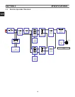
Page 16: ...3 0 16 section 3 SPECIFICATIONS 3 4 Machine Operation Flowchart...
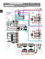
Page 27: ...4 2 27 4 2 Control Transformer T2 0558007188 SECTION 4 DESCRIPTION OF OPERATION...
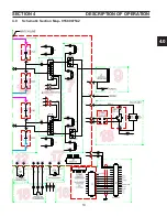
Page 30: ...4 3 30 4 3 Input Bridge 0558007068 0558007077 SECTION 4 DESCRIPTION OF OPERATION...
Page 35: ...4 6 35 blank...
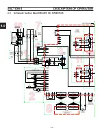
Page 38: ...4 8 38 4 8 PCB1 Control Board 0558038317 SECTION 4 DESCRIPTION OF OPERATION 4 10 6 8 5 3 11 7...
Page 52: ...4 8 52 4 8 14 PCB1 Layout 0558038317 SECTION 4 DESCRIPTION OF OPERATION...
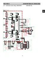
Page 60: ...4 10 60 4 10 2 Power PC Board Schematic 2 0558038315 SECTION 4 DESCRIPTION OF OPERATION 3 14 8...
Page 67: ...4 10 67 4 10 7 Power Board_PCB2 Control Relays 0558038315 SECTION 4 DESCRIPTION OF OPERATION...
Page 77: ...4 10 77 4 10 16 Buss Supply IGBT SECTION 4 DESCRIPTION OF OPERATION...
Page 91: ...4 11 91 4 11 Power Driver 0558038335 SECTION 4 DESCRIPTION OF OPERATION...
Page 109: ...4 19 109 SECTION 4 DESCRIPTION OF OPERATION 4 19 PT38 Plasma Torch...
Page 110: ...4 19 110 SECTION 4 DESCRIPTION OF OPERATION 4 19 PT38 Plasma Torch...
Page 113: ...5 0 113 5 1 Wiring Diagram 230 460 Volt 0558007543 section 5 WIring diagrams...
Page 114: ...5 0 114 5 1 Wiring Diagram 230 460 Volt 0558007543 section 5 WIring diagrams...
Page 115: ...5 0 115 5 1 Wiring Diagram 230 460 Volt 0558007543 section 5 WIring diagrams...
Page 116: ...5 0 116 section 5 WIring diagrams 5 1 Wiring Diagram 230 460 Volt 0558007543...
Page 117: ...5 0 117 section 5 WIring diagrams 5 1 Wiring Diagram 230 460 Volt 0558007543...
Page 118: ...5 0 118 5 2 Wiring Diagram 400 400V CE 0558007547 section 5 WIring diagrams...
Page 119: ...5 0 119 section 5 WIring diagrams 5 2 Wiring Diagram 400 400V CE 0558007547...
Page 120: ...5 0 120 5 2 Wiring Diagram 400 400V CE 0558007547 section 5 WIring diagrams...
Page 121: ...5 0 121 section 5 WIring diagrams 5 2 Wiring Diagram 400 400V CE 0558007547...
Page 122: ...5 0 122 5 2 Wiring Diagram 400 400V CE 0558007547 section 5 WIring diagrams...
Page 123: ...5 0 123 section 5 WIring diagrams 5 2 Wiring Diagram 400 400V CE 0558007547...
Page 124: ...124 5 3 Wiring Diagram 575V 0558007545 section 5 WIring diagrams...
Page 125: ...125 section 5 WIring diagrams 5 3 Wiring Diagram 575V 0558007545...
Page 126: ...126 5 3 Wiring Diagram 575V 0558007545 section 5 WIring diagrams...
Page 127: ...127 section 5 WIring diagrams 5 3 Wiring Diagram 575V 0558007545...
Page 128: ...128 5 3 Wiring Diagram 575V 0558007545 section 5 WIring diagrams...
Page 129: ...129 section 5 WIring diagrams 5 3 Wiring Diagram 575V 0558007545...
Page 130: ...130 blank...
Page 135: ...6 0 blank 135...
Page 136: ...6 0 136 section 6 replacement parts 6 3 Front 0558007540...
Page 140: ...6 0 140 6 3 Top 0558007540 section 6 replacement parts...
Page 144: ...6 0 144 section 6 replacement parts 6 3 Left Inside2 0558007540...
Page 146: ...6 0 146 section 6 replacement parts 6 3 Rear View 0558007540...
Page 148: ...6 0 148 6 3 Front Rear Isometric Views 0558007540 section 6 replacement parts...
Page 159: ...159 section 7 mechanized conversion 20 Trim all tie wraps and replace the unit s cover...
Page 166: ...10 166 SECTION 9 General information 10 3 Ohm s and Watt s Laws...
Page 171: ...10 171 10 6 Ohm Testing SECTION 9 General information...
Page 172: ...10 172 10 7 Diode Testing SECTION 9 General information...
Page 173: ...10 173 10 8 Ripple SECTION 9 General information...
Page 174: ...10 174 10 9 Voltage Measurement SECTION 9 General information...
Page 178: ...10 178 IGBT Tester Schematic 10 10 1 IGBT Testing SECTION 8 General information...
Page 182: ...182 revision history Original release 11 2008 1...


