1.0
8
Standard P-1, “Precautions for Safe Handling of
Compressed Gases in Cylinders”, which is avail-
able from Compressed Gas Association, 1235 Jef-
ferson Davis Highway, Arlington, VA 22202.
EQUIPMENT MAINTENANCE -- Faulty
or improperly maintained equipment can
cause injury or death. Therefore:
1.
Always have
qualified
personnel perform
the installation, troubleshooting, and maintenance
work. Do not perform any electrical work unless
you are
qualified
to perform such work.
2.
Before performing any maintenance work
inside a power source, disconnect the power
source from the incoming electrical power.
3.
Maintain cables, grounding wire, connec-
tions, power cord, and power supply in safe work-
ing order. Do not operate any equipment in faulty
condition.
4.
Do not abuse any equipment or acces-
sories. Keep equipment away from heat sources
such as furnaces, wet conditions such as water
puddles, oil or grease, corrosive atmospheres and
inclement weather.
5.
Keep all safety devices and cabinet covers
in position and in good repair.
6.
Use equipment only for its intended pur-
pose. Do not modify it in any manner.
3.
If you develop momentary eye, nose, or
throat irritation while operating, this is an indication
that ventilation is not adequate. Stop work and take
necessary steps to improve ventilation in the work
area. Do not continue to operate if physical dis-
comfort persists.
4.
Refer to ANSI/ASC Standard Z49.1 (see
listing below) for
specific
ventilation
recommenda
-
tions.
5.
WARNING: This product, when used for
welding or cutting, produces fumes or gases which
contain chemicals known to the State of California
to cause birth defects and, in some cases, cancer.
(California Health & Safety Code §25249.5 et seq.)
CYLINDER HANDLING -- Cylinders,
if mishandled, can rupture and vio-
lently release gas. Sudden rupture
of cylinder, valve, or relief device can
injure or kill. Therefore:
1.
Use the proper gas for the process and use
the proper pressure reducing regulator designed to
operate from the compressed gas cylinder. Do not
use
adaptors.
Maintain hoses
and
fittings
in
good
condition. Follow manufacturer’s operating instruc-
tions for mounting regulator to a compressed gas
cylinder.
2.
Always secure cylinders in an upright posi-
tion by chain or strap to suitable hand trucks, un-
dercarriages, benches, walls, post, or racks. Never
secure
cylinders
to work tables or
fixtures
where
they may become part of an electrical circuit.
3.
When not in use, keep cylinder valves
closed. Have valve protection cap in place if regu-
lator is not connected. Secure and move cylinders
by using suitable hand trucks. Avoid rough han-
dling of cylinders.
4.
Locate cylinders away from heat, sparks,
and
flames.
Never strike an arc on a
cylinder.
5.
For additional information, refer to CGA
SECTION 1
SAfETY PRECAuTIONS
Summary of Contents for PowerCut 1600
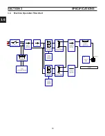
Page 16: ...3 0 16 section 3 SPECIFICATIONS 3 4 Machine Operation Flowchart...
Page 27: ...4 2 27 4 2 Control Transformer T2 0558007188 SECTION 4 DESCRIPTION OF OPERATION...
Page 30: ...4 3 30 4 3 Input Bridge 0558007068 0558007077 SECTION 4 DESCRIPTION OF OPERATION...
Page 35: ...4 6 35 blank...
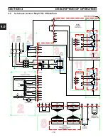
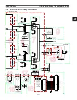
Page 38: ...4 8 38 4 8 PCB1 Control Board 0558038317 SECTION 4 DESCRIPTION OF OPERATION 4 10 6 8 5 3 11 7...
Page 52: ...4 8 52 4 8 14 PCB1 Layout 0558038317 SECTION 4 DESCRIPTION OF OPERATION...
Page 60: ...4 10 60 4 10 2 Power PC Board Schematic 2 0558038315 SECTION 4 DESCRIPTION OF OPERATION 3 14 8...
Page 67: ...4 10 67 4 10 7 Power Board_PCB2 Control Relays 0558038315 SECTION 4 DESCRIPTION OF OPERATION...
Page 77: ...4 10 77 4 10 16 Buss Supply IGBT SECTION 4 DESCRIPTION OF OPERATION...
Page 91: ...4 11 91 4 11 Power Driver 0558038335 SECTION 4 DESCRIPTION OF OPERATION...
Page 109: ...4 19 109 SECTION 4 DESCRIPTION OF OPERATION 4 19 PT38 Plasma Torch...
Page 110: ...4 19 110 SECTION 4 DESCRIPTION OF OPERATION 4 19 PT38 Plasma Torch...
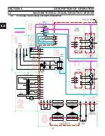
Page 113: ...5 0 113 5 1 Wiring Diagram 230 460 Volt 0558007543 section 5 WIring diagrams...
Page 114: ...5 0 114 5 1 Wiring Diagram 230 460 Volt 0558007543 section 5 WIring diagrams...
Page 115: ...5 0 115 5 1 Wiring Diagram 230 460 Volt 0558007543 section 5 WIring diagrams...
Page 116: ...5 0 116 section 5 WIring diagrams 5 1 Wiring Diagram 230 460 Volt 0558007543...
Page 117: ...5 0 117 section 5 WIring diagrams 5 1 Wiring Diagram 230 460 Volt 0558007543...
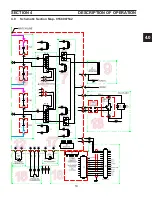
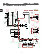
Page 118: ...5 0 118 5 2 Wiring Diagram 400 400V CE 0558007547 section 5 WIring diagrams...
Page 119: ...5 0 119 section 5 WIring diagrams 5 2 Wiring Diagram 400 400V CE 0558007547...
Page 120: ...5 0 120 5 2 Wiring Diagram 400 400V CE 0558007547 section 5 WIring diagrams...
Page 121: ...5 0 121 section 5 WIring diagrams 5 2 Wiring Diagram 400 400V CE 0558007547...
Page 122: ...5 0 122 5 2 Wiring Diagram 400 400V CE 0558007547 section 5 WIring diagrams...
Page 123: ...5 0 123 section 5 WIring diagrams 5 2 Wiring Diagram 400 400V CE 0558007547...
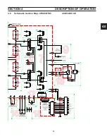
Page 124: ...124 5 3 Wiring Diagram 575V 0558007545 section 5 WIring diagrams...
Page 125: ...125 section 5 WIring diagrams 5 3 Wiring Diagram 575V 0558007545...
Page 126: ...126 5 3 Wiring Diagram 575V 0558007545 section 5 WIring diagrams...
Page 127: ...127 section 5 WIring diagrams 5 3 Wiring Diagram 575V 0558007545...
Page 128: ...128 5 3 Wiring Diagram 575V 0558007545 section 5 WIring diagrams...
Page 129: ...129 section 5 WIring diagrams 5 3 Wiring Diagram 575V 0558007545...
Page 130: ...130 blank...
Page 135: ...6 0 blank 135...
Page 136: ...6 0 136 section 6 replacement parts 6 3 Front 0558007540...
Page 140: ...6 0 140 6 3 Top 0558007540 section 6 replacement parts...
Page 144: ...6 0 144 section 6 replacement parts 6 3 Left Inside2 0558007540...
Page 146: ...6 0 146 section 6 replacement parts 6 3 Rear View 0558007540...
Page 148: ...6 0 148 6 3 Front Rear Isometric Views 0558007540 section 6 replacement parts...
Page 159: ...159 section 7 mechanized conversion 20 Trim all tie wraps and replace the unit s cover...
Page 166: ...10 166 SECTION 9 General information 10 3 Ohm s and Watt s Laws...
Page 171: ...10 171 10 6 Ohm Testing SECTION 9 General information...
Page 172: ...10 172 10 7 Diode Testing SECTION 9 General information...
Page 173: ...10 173 10 8 Ripple SECTION 9 General information...
Page 174: ...10 174 10 9 Voltage Measurement SECTION 9 General information...
Page 178: ...10 178 IGBT Tester Schematic 10 10 1 IGBT Testing SECTION 8 General information...
Page 182: ...182 revision history Original release 11 2008 1...