
4.14
97
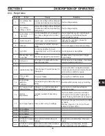
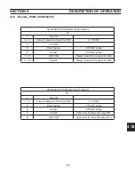
Code
Error
Cause
Solution
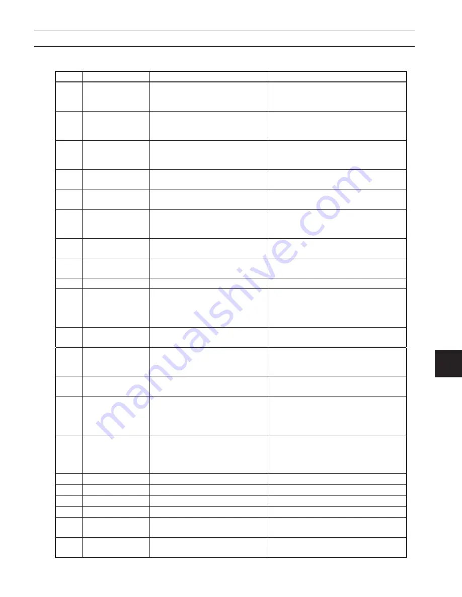
1
Line voltage, idle
+/- 15 %
Supply line voltage either dropped
or exceeded nominal input setting.
Check voltage supply.
2
Line voltage,
c/- 20 %
Supply line voltage either dropped
or exceeded nominal input setting
during a cut.
Check voltage supply.
3
Control bias, +/- 15
V bias split
Control transformer not supplying
the proper voltage to the control
circuit
Check transformer and control board.
Send unit to an Authorized Repair
Station(ARS) for repair.
4
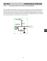
Thermal switch
Switch open - unit overheated.
Allow unit to cool down, check for
adequate ventilation.
5
Pressure
Air pressure is outside of proper
range.
Check air supply and pressure setting.
6
Fail to fire
Arc did not transfer. Arc will
repeatedly “pop” out 3 consecutive
times.
Check/replace consumables.
7
Pilot Arc time out (~
5 seconds)
Pilot arc exceeded 5 second limit .
Transfer within 5 second limit. Check
ground cable.
8
Torch error
Electrode in contact with nozzle
(failed to separate).
Check/replace consumables. If problem
persists replace/repair torch.
9
10
Feedback improper
Primarily seen if current sensor is
unplugged.
Check cable and connection between
current sensor board and control board.
Send unit to an ARS for repair.
11
Primary over-
current
Converter failure.
Send unit to an ARS for repair.
12
Single phase
operation,
shutdown
Exceeded single phase duty cycle
rating.
Operate within proper duty cycle rating.
13
OCV (open circuit
voltage) failure
Voltage or current not detected
when test (PIP) is performed.
Send unit to an Authorized Repair
Station for repair.
14
Cabinet
temperature
Too high, outside of operating
limits.
Check ventilation around unit.Check
air louvers and any other openings to
ensure that any obstruction is removed.
15
Bus charger failure Primary bus not up to voltage.
Check bus charger. Send unit to an ARS
for repair.
Effective Prog.Ver 1.03. Error 15 will
reset with “power off/on
16
Not Available
17
Not Available
18
Not Available
19
Not Available
20
PIP (Parts in place)
no retract
Piston did not retract when air
applied.
Check/clean consumables. Check air
supply.
21
PIP (Parts in place)
no continuity
Piston did not drop back in place
when air was removed.
Check/clean consumables. Ensure
proper installation of consumables.
4.14 Help Codes
SECTION 4
DESCRIPTION Of OPERATION
Summary of Contents for PowerCut 1600
Page 16: ...3 0 16 section 3 SPECIFICATIONS 3 4 Machine Operation Flowchart...
Page 27: ...4 2 27 4 2 Control Transformer T2 0558007188 SECTION 4 DESCRIPTION OF OPERATION...
Page 30: ...4 3 30 4 3 Input Bridge 0558007068 0558007077 SECTION 4 DESCRIPTION OF OPERATION...
Page 35: ...4 6 35 blank...
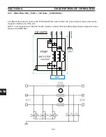
Page 38: ...4 8 38 4 8 PCB1 Control Board 0558038317 SECTION 4 DESCRIPTION OF OPERATION 4 10 6 8 5 3 11 7...
Page 52: ...4 8 52 4 8 14 PCB1 Layout 0558038317 SECTION 4 DESCRIPTION OF OPERATION...
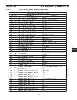
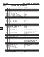
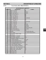
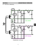
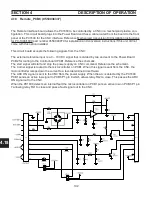
Page 60: ...4 10 60 4 10 2 Power PC Board Schematic 2 0558038315 SECTION 4 DESCRIPTION OF OPERATION 3 14 8...
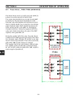
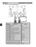
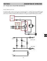
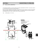
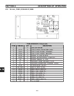
Page 67: ...4 10 67 4 10 7 Power Board_PCB2 Control Relays 0558038315 SECTION 4 DESCRIPTION OF OPERATION...
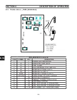
Page 77: ...4 10 77 4 10 16 Buss Supply IGBT SECTION 4 DESCRIPTION OF OPERATION...
Page 91: ...4 11 91 4 11 Power Driver 0558038335 SECTION 4 DESCRIPTION OF OPERATION...
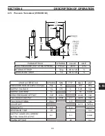
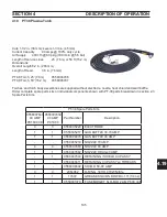
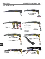
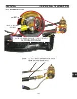
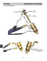
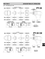
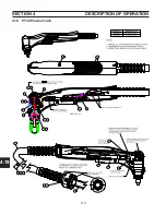
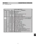
Page 109: ...4 19 109 SECTION 4 DESCRIPTION OF OPERATION 4 19 PT38 Plasma Torch...
Page 110: ...4 19 110 SECTION 4 DESCRIPTION OF OPERATION 4 19 PT38 Plasma Torch...
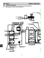
Page 113: ...5 0 113 5 1 Wiring Diagram 230 460 Volt 0558007543 section 5 WIring diagrams...
Page 114: ...5 0 114 5 1 Wiring Diagram 230 460 Volt 0558007543 section 5 WIring diagrams...
Page 115: ...5 0 115 5 1 Wiring Diagram 230 460 Volt 0558007543 section 5 WIring diagrams...
Page 116: ...5 0 116 section 5 WIring diagrams 5 1 Wiring Diagram 230 460 Volt 0558007543...
Page 117: ...5 0 117 section 5 WIring diagrams 5 1 Wiring Diagram 230 460 Volt 0558007543...
Page 118: ...5 0 118 5 2 Wiring Diagram 400 400V CE 0558007547 section 5 WIring diagrams...
Page 119: ...5 0 119 section 5 WIring diagrams 5 2 Wiring Diagram 400 400V CE 0558007547...
Page 120: ...5 0 120 5 2 Wiring Diagram 400 400V CE 0558007547 section 5 WIring diagrams...
Page 121: ...5 0 121 section 5 WIring diagrams 5 2 Wiring Diagram 400 400V CE 0558007547...
Page 122: ...5 0 122 5 2 Wiring Diagram 400 400V CE 0558007547 section 5 WIring diagrams...
Page 123: ...5 0 123 section 5 WIring diagrams 5 2 Wiring Diagram 400 400V CE 0558007547...
Page 124: ...124 5 3 Wiring Diagram 575V 0558007545 section 5 WIring diagrams...
Page 125: ...125 section 5 WIring diagrams 5 3 Wiring Diagram 575V 0558007545...
Page 126: ...126 5 3 Wiring Diagram 575V 0558007545 section 5 WIring diagrams...
Page 127: ...127 section 5 WIring diagrams 5 3 Wiring Diagram 575V 0558007545...
Page 128: ...128 5 3 Wiring Diagram 575V 0558007545 section 5 WIring diagrams...
Page 129: ...129 section 5 WIring diagrams 5 3 Wiring Diagram 575V 0558007545...
Page 130: ...130 blank...
Page 135: ...6 0 blank 135...
Page 136: ...6 0 136 section 6 replacement parts 6 3 Front 0558007540...
Page 140: ...6 0 140 6 3 Top 0558007540 section 6 replacement parts...
Page 144: ...6 0 144 section 6 replacement parts 6 3 Left Inside2 0558007540...
Page 146: ...6 0 146 section 6 replacement parts 6 3 Rear View 0558007540...
Page 148: ...6 0 148 6 3 Front Rear Isometric Views 0558007540 section 6 replacement parts...
Page 159: ...159 section 7 mechanized conversion 20 Trim all tie wraps and replace the unit s cover...
Page 166: ...10 166 SECTION 9 General information 10 3 Ohm s and Watt s Laws...
Page 171: ...10 171 10 6 Ohm Testing SECTION 9 General information...
Page 172: ...10 172 10 7 Diode Testing SECTION 9 General information...
Page 173: ...10 173 10 8 Ripple SECTION 9 General information...
Page 174: ...10 174 10 9 Voltage Measurement SECTION 9 General information...
Page 178: ...10 178 IGBT Tester Schematic 10 10 1 IGBT Testing SECTION 8 General information...
Page 182: ...182 revision history Original release 11 2008 1...