486
APARTADO 4
FUNCIONAMIENTO
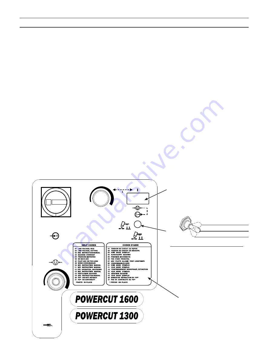
D. Disparador del soplete / Conmutador de prueba del gas
Modos de funcionamiento:
Disparador normal
(posición CENTRO): La configuración se utilizará para la mayoría de las operaciones de perforación
y de corte. El operario debe sostener apretado el conmutador del soplete durante toda la operación de corte y debe
soltarlo al final del corte. Recomendado para corte normal, corte expandido de metal / en rejilla, y perforación.
Bloqueo del disparador
(posición ABAJO): Permite que se suelte el conmutador del soplete después del arranque y
ya se ha iniciado el arco de corte. Para extinguir el arco al final del corte, pulse y suelte el conmutador del soplete de
nuevo o separe el soplete del trabajo. No recomendado para corte expandido de metal / en rejilla.
Modo de prueba:
Conmutador de prueba de gas
(posición ARRIBA): La pantalla de visualización indicará la presión del flujo del aire.
El regulador de aire debe ajustarse a la presión recomendada antes de las operaciones de corte. Deje que el aire
fluya durante unos minutos. Esto debería eliminar cualquier condensación que pueda haberse acumulado durante
el período de bloqueo. Asegúrese de que coloca el conmutador en
Disparador normal
o
Bloqueo del disparador
antes de comenzar las operaciones de corte.
E. Pantalla de visualización:
Muestra la configuración de corriente durante el funcionamiento normal.
1. Indicación de encendido:
Cuando la unidad se enciende inicialmente, se muestran brevemente el Modelo, las PIP
(Piezas en Posición), y la versión de software. Después, la pantalla mostrará la configuración de corriente.
2. Prueba de gas:
Cuando la unidad está en modo "PRUEBA DE GAS", la pantalla indicará la configuración de presión
del aire en psi/bares.
E
F
Los Códigos de Error se
muestran en las unidades
de inglés e inglés-francés
únicamente
D
posición ARRIBA
posición CENTRO
posición ABAJO
Detalle del conmutador de palanca
Figura 4-2. Controles de Powercut 1300/1600
Summary of Contents for Powercut-1600
Page 4: ...4 table of contents ...
Page 11: ...11 MANUEL PLASMARC SKÆREENHED Powercut 1300 1600 ...
Page 12: ...12 ...
Page 24: ...24 SEKTION 3 INSTALLATION ...
Page 32: ...32 SEKTION 4 BETJENING ...
Page 33: ...33 MEKANISERET PLASMARC SKÆREENHED Powercut 1300 1600 ...
Page 34: ...34 ...
Page 57: ...57 HANDMATIG PLASMARC SNIJPAKKET Powercut 1300 1600 ...
Page 58: ...58 ...
Page 70: ...70 HOOFDSTUK 3 INSTALLATIE ...
Page 78: ...78 HOOFDSTUK 4 BEDIENING ...
Page 79: ...79 MACHINAAL PLASMARC SNIJPAKKET Powercut 1300 1600 ...
Page 80: ...80 ...
Page 103: ...103 MANUAL PLASMARC CUTTING PACKAGE Powercut 1300 1600 ...
Page 104: ...104 ...
Page 116: ...116 SECTION 3 INSTALLATION ...
Page 124: ...124 section 4 operation ...
Page 125: ...125 MECHANIZED PLASMARC CUTTING PACKAGE Powercut 1300 1600 ...
Page 126: ...126 ...
Page 149: ...149 MANUAALINEN PLASMARC LEIKKAUSJÄRJESTELMÄ Powercut 1300 1600 ...
Page 150: ...150 ...
Page 162: ...162 OSA 3 ASENNUS ...
Page 170: ...170 OSA 4 KÄYTTÖ ...
Page 171: ...171 MEKAANINEN PLASMARC LEIKKAUSJÄRJESTELMÄ Powercut 1300 1600 ...
Page 172: ...172 ...
Page 195: ...195 ENSEMBLE DE COUPAGE MANUEL À L ARC PLASMA Powercut 1300 1600 ...
Page 196: ...196 ...
Page 208: ...208 SECTION 3 INSTALLATION ...
Page 216: ...216 section 4 FONCTIONNEMENT ...
Page 217: ...217 ENSEMBLE DE COUPAGE À L ARC PLASMA AUTOMATIQUE Powercut 1300 1600 ...
Page 218: ...218 ...
Page 241: ...241 PLASMARC SCHNEIDAUSRÜSTUNG FÜR MANUELLES PLASMASCHNEIDEN Powercut 1300 1600 ...
Page 242: ...242 ...
Page 254: ...254 ABSCHNITT 3 INSTALLATION ...
Page 262: ...262 ABSCHNITT 4 BETRIEB ...
Page 263: ...263 PLASMARC SCHNEIDAUSRÜSTUNG FÜR MECHANISIERTES PLASMASCHNEIDEN Powercut 1300 1600 ...
Page 264: ...264 ...
Page 287: ...287 PACCHETTO DI TAGLIO PLASMARC MANUALE Powercut 1300 1600 ...
Page 288: ...288 ...
Page 300: ...300 SEZIONE 3 INSTALLAZIONE ...
Page 308: ...308 SEZIONE 4 FUNZIONAMENTO ...
Page 309: ...309 PACCHETTO DI TAGLIO PLASMARC MECCANIZZATO Powercut 1300 1600 ...
Page 310: ...310 ...
Page 333: ...333 MANUELL PLASMARC SKJÆREPAKKE Powercut 1300 1600 ...
Page 334: ...334 ...
Page 346: ...346 KAPITTEL 3 INSTALLASJON ...
Page 354: ...354 KAPITTEL 4 BRUK ...
Page 355: ...355 MEKANISERT PLASMARC SKJÆREPAKKE Powercut 1300 1600 ...
Page 356: ...356 ...
Page 379: ...379 ZESTAW DO RĘCZNEGO CIĘCIA ŁUKIEM PLAZMOWYM Powercut 1300 1600 ...
Page 380: ...380 ...
Page 392: ...392 ROZDZIAŁ 3 INSTALACJA ...
Page 400: ...400 ROZDZIAŁ 4 EKSPLOATACJA ...
Page 401: ...401 ZESTAW DO ZMECHANIZOWANEGO CIĘCIA ŁUKIEM PLAZMOWYM Powercut 1300 1600 ...
Page 402: ...402 ...
Page 425: ...425 CONJUNTO DE CORTE DE ARCO DE PLASMA MANUAL Powercut 1300 1600 ...
Page 426: ...426 ...
Page 438: ...438 CAPÍTULO 3 INSTALAÇÃO ...
Page 446: ...446 CAPÍTULO 4 FUNCIONAMENTO ...
Page 447: ...447 CONJUNTO DE CORTE DE ARCO DE PLASMA MECANIZADO Powercut 1300 1600 ...
Page 448: ...448 ...
Page 471: ...471 PAQUETE DE CORTE PLASMARC MANUAL Powercut 1300 1600 ...
Page 472: ...472 ...
Page 484: ...484 APARTADO 3 INSTALACIÓN ...
Page 492: ...492 APARTADO 4 FUNCIONAMIENTO ...
Page 493: ...493 PAQUETE DE CORTE PLASMARC MECANIZADO Powercut 1300 1600 ...
Page 494: ...494 ...
Page 517: ...517 MANUELLT PLASMARC SKÄRPAKET Powercut 1300 1600 ...
Page 518: ...518 ...
Page 530: ...530 AVSNITT 3 INSTALLATION ...
Page 538: ...538 AVSNITT 4 ANVÄNDNING ...
Page 539: ...539 MEKANISERAT PLASMARC SKÄRPAKET Powercut 1300 1600 ...
Page 540: ...540 ...
Page 557: ...557 Powercut 1300 1600 MAINTENANCE TROUBLESHOOTING SCHEMATIC DIAGRAMS REPLACEMENT PARTS ...
Page 558: ...558 ...
Page 562: ...562 section 5 maintenance ...


