3.0
17
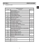
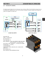
3.5
Component locator
SECTION 3
SPECIfICATIONS
C37, C40,
C44,C47,
BUSS CAPACITORS
10.16
C101, C102,
C103, C104
BUSS CAPACITORS
10.16
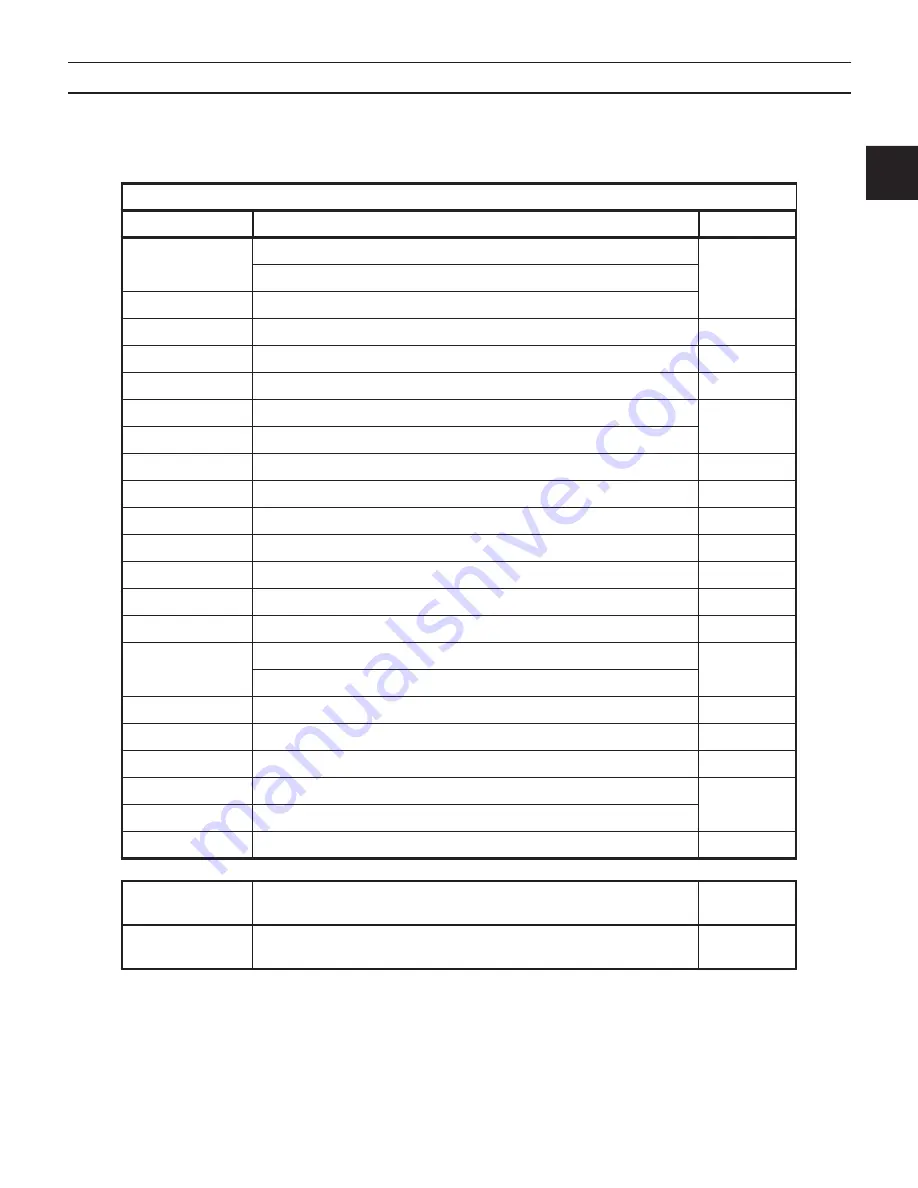
PC1600 Components
Symbol
Description
Section # 4.
L1
INDUCTOR INPUT
9
REACTOR LINE 3 PHASE
L2
INDUCTOR OUTPUT
T1
TRANSFORMER MAIN
6
T2
TRANSFORMER CONTROL
2
BR1
BRIDGE RECTIFIER 110A 1600V
3
Q101,102
IGBT DUAL 150A 600V
5
Q103
IGBT 50A 1200V
D101,102
DIODE MODULE 100A 600V
7
PCB1
PC BOARD - CONTROL / DISPLAY
8
PCB2
PC BOARD - POWER
10
PCB3,4
PC BOARD - DRIVER BOARD
11
PCB5
PC BOARD - PILOT ARC DRIVER BOARD
13
PCB6
PC BOARD - REMOTE
18
PCB7
PC BOARD - EMC FILTER 50A
16
K1
RELAY SPST 24VAC 20A(110VDC) w/ MAG BLOWOUT
4
CONTACTOR 3P 40A 24VAC
M1
FAN 6” 230CFM 230V
2
SW1
SWITCH POWER 3P 60A 600V
1
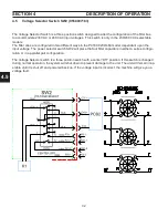
SW2
SWITCH VOLTAGE SELECTOR
5
TS1
SWITCH THERMAL N/C 176°F
12
TS2
SWITCH THERMAL N/C 176°F - Solder
SOL1
SOLENOID
17
Summary of Contents for PowerCut 1600
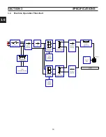
Page 16: ...3 0 16 section 3 SPECIFICATIONS 3 4 Machine Operation Flowchart...
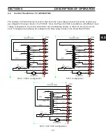
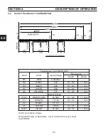
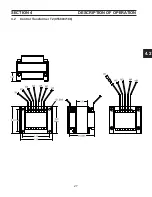
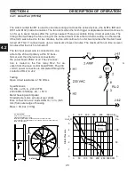
Page 27: ...4 2 27 4 2 Control Transformer T2 0558007188 SECTION 4 DESCRIPTION OF OPERATION...
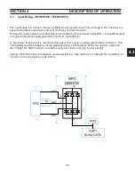
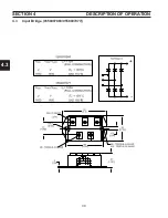
Page 30: ...4 3 30 4 3 Input Bridge 0558007068 0558007077 SECTION 4 DESCRIPTION OF OPERATION...
Page 35: ...4 6 35 blank...
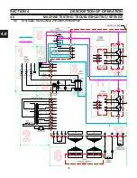
Page 38: ...4 8 38 4 8 PCB1 Control Board 0558038317 SECTION 4 DESCRIPTION OF OPERATION 4 10 6 8 5 3 11 7...
Page 52: ...4 8 52 4 8 14 PCB1 Layout 0558038317 SECTION 4 DESCRIPTION OF OPERATION...
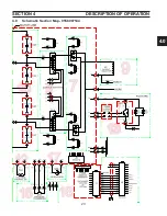
Page 60: ...4 10 60 4 10 2 Power PC Board Schematic 2 0558038315 SECTION 4 DESCRIPTION OF OPERATION 3 14 8...
Page 67: ...4 10 67 4 10 7 Power Board_PCB2 Control Relays 0558038315 SECTION 4 DESCRIPTION OF OPERATION...
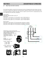
Page 77: ...4 10 77 4 10 16 Buss Supply IGBT SECTION 4 DESCRIPTION OF OPERATION...
Page 91: ...4 11 91 4 11 Power Driver 0558038335 SECTION 4 DESCRIPTION OF OPERATION...
Page 109: ...4 19 109 SECTION 4 DESCRIPTION OF OPERATION 4 19 PT38 Plasma Torch...
Page 110: ...4 19 110 SECTION 4 DESCRIPTION OF OPERATION 4 19 PT38 Plasma Torch...
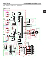
Page 113: ...5 0 113 5 1 Wiring Diagram 230 460 Volt 0558007543 section 5 WIring diagrams...
Page 114: ...5 0 114 5 1 Wiring Diagram 230 460 Volt 0558007543 section 5 WIring diagrams...
Page 115: ...5 0 115 5 1 Wiring Diagram 230 460 Volt 0558007543 section 5 WIring diagrams...
Page 116: ...5 0 116 section 5 WIring diagrams 5 1 Wiring Diagram 230 460 Volt 0558007543...
Page 117: ...5 0 117 section 5 WIring diagrams 5 1 Wiring Diagram 230 460 Volt 0558007543...
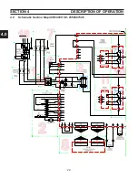
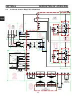
Page 118: ...5 0 118 5 2 Wiring Diagram 400 400V CE 0558007547 section 5 WIring diagrams...
Page 119: ...5 0 119 section 5 WIring diagrams 5 2 Wiring Diagram 400 400V CE 0558007547...
Page 120: ...5 0 120 5 2 Wiring Diagram 400 400V CE 0558007547 section 5 WIring diagrams...
Page 121: ...5 0 121 section 5 WIring diagrams 5 2 Wiring Diagram 400 400V CE 0558007547...
Page 122: ...5 0 122 5 2 Wiring Diagram 400 400V CE 0558007547 section 5 WIring diagrams...
Page 123: ...5 0 123 section 5 WIring diagrams 5 2 Wiring Diagram 400 400V CE 0558007547...
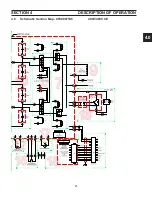
Page 124: ...124 5 3 Wiring Diagram 575V 0558007545 section 5 WIring diagrams...
Page 125: ...125 section 5 WIring diagrams 5 3 Wiring Diagram 575V 0558007545...
Page 126: ...126 5 3 Wiring Diagram 575V 0558007545 section 5 WIring diagrams...
Page 127: ...127 section 5 WIring diagrams 5 3 Wiring Diagram 575V 0558007545...
Page 128: ...128 5 3 Wiring Diagram 575V 0558007545 section 5 WIring diagrams...
Page 129: ...129 section 5 WIring diagrams 5 3 Wiring Diagram 575V 0558007545...
Page 130: ...130 blank...
Page 135: ...6 0 blank 135...
Page 136: ...6 0 136 section 6 replacement parts 6 3 Front 0558007540...
Page 140: ...6 0 140 6 3 Top 0558007540 section 6 replacement parts...
Page 144: ...6 0 144 section 6 replacement parts 6 3 Left Inside2 0558007540...
Page 146: ...6 0 146 section 6 replacement parts 6 3 Rear View 0558007540...
Page 148: ...6 0 148 6 3 Front Rear Isometric Views 0558007540 section 6 replacement parts...
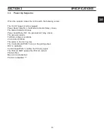
Page 159: ...159 section 7 mechanized conversion 20 Trim all tie wraps and replace the unit s cover...
Page 166: ...10 166 SECTION 9 General information 10 3 Ohm s and Watt s Laws...
Page 171: ...10 171 10 6 Ohm Testing SECTION 9 General information...
Page 172: ...10 172 10 7 Diode Testing SECTION 9 General information...
Page 173: ...10 173 10 8 Ripple SECTION 9 General information...
Page 174: ...10 174 10 9 Voltage Measurement SECTION 9 General information...
Page 178: ...10 178 IGBT Tester Schematic 10 10 1 IGBT Testing SECTION 8 General information...
Page 182: ...182 revision history Original release 11 2008 1...


