14
SECTION 3
OPERATION
3.1 OPERATION
ELECTRIC SHOCK can kill.
• Do NOT operate the unit with the cover
removed.
• Do NOT apply power to the unit while hold-
ing or carrying the unit.
• Do NOT touch any torch parts forward of the
torch handle (nozzle, heat shield, electrode,
etc.) with power switch on.
ARC RAYS can burn eyes and skin;
NOISE can damage hearing.
• Wear welding helmet with No. 6 or 7 lens
shade.
• Wear eye, ear, and body protection.
Position the PowerCut-550 at least 10 feet (3
meters) from the cutting area. Sparks and hot
slag from the cutting operation can damage
the unit.
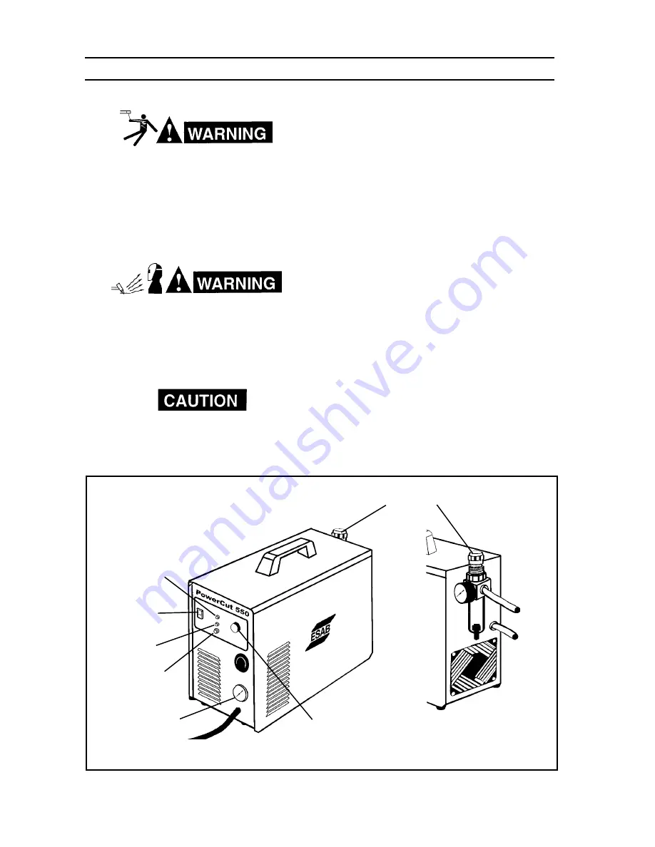
3.2 PowerCut-550 CONTROLS
(FIGURE 3-1)
A.
Power Switch (located on front panel).
When
placed in ON position, the white pilot light will
glow indicating control circuit is energized and
the cooling fan will run.
B.
Output Current Control.
Adjustable from 15
to 35 amperes to suit cutting conditions.
C.
Air Check Push Button Switch.
When ener-
gized, air filter-regulator can be adjusted to
desired pressure (55-65 psig) before cutting
operations. Allow air to flow for a few minutes.
This should remove any condensation that
may have accumulated during shutdown pe-
riod. After setting the pressure, release the
button to its normal position.
Figure 3-1. PowerCut 550 Controls
AIR REGULATOR
CONTROL KNOB
AIR PRESSURE
GAUGE
CURRENT
CONTROL
KNOB
REAR
VIEW
POWER ON-OFF
(I-O) SWITCH &
CIRCUIT BREAKER
AIR CHECK
BUTTON
FAULT LIGHT
AMBER
AIR LIGHT
GREEN


