background image

18

SECTION  4

 MAINTENANCE

4.1  GENERAL

If this equipment does not operate properly,
stop work immediately and investigate the cause
of the malfunction.  Maintenance work must be
performed by an experienced person, and elec-
trical work by a trained electrician.  Do not permit
untrained persons to inspect, clean, or repair
this equipment.  Use only recommended re-
placement parts.

Be sure that the wall disconnect switch or wall
circuit breaker is open before attempting any
inspection or work inside of the PowerCut-
550.

4.2  INSPECTION AND CLEANING

Frequent inspection and cleaning of the PowerCut-
550 is recommended for safety and proper opera-
tion.  Some suggestions for inspecting and cleaning
are as follows:

A.

Check work cable to workpiece connection.

B.

Check safety earth ground at workpiece and at
power source chassis.

C.

Check heat shield on torch.  It should be
replaced if damaged.

D.

Check the torch electrode and cutting nozzle
for wear on a daily basis.  Remove spatter or
replace if necessary.

E.

Make sure cable and hoses are not damaged
or kinked.

F.

Make sure all fittings and ground connections
are tight.

Water or oil occasionally accumulates in com-
pressed air lines.  Be sure to direct the first blast
of air away from the equipment to avoid damage
to the PowerCut-550.

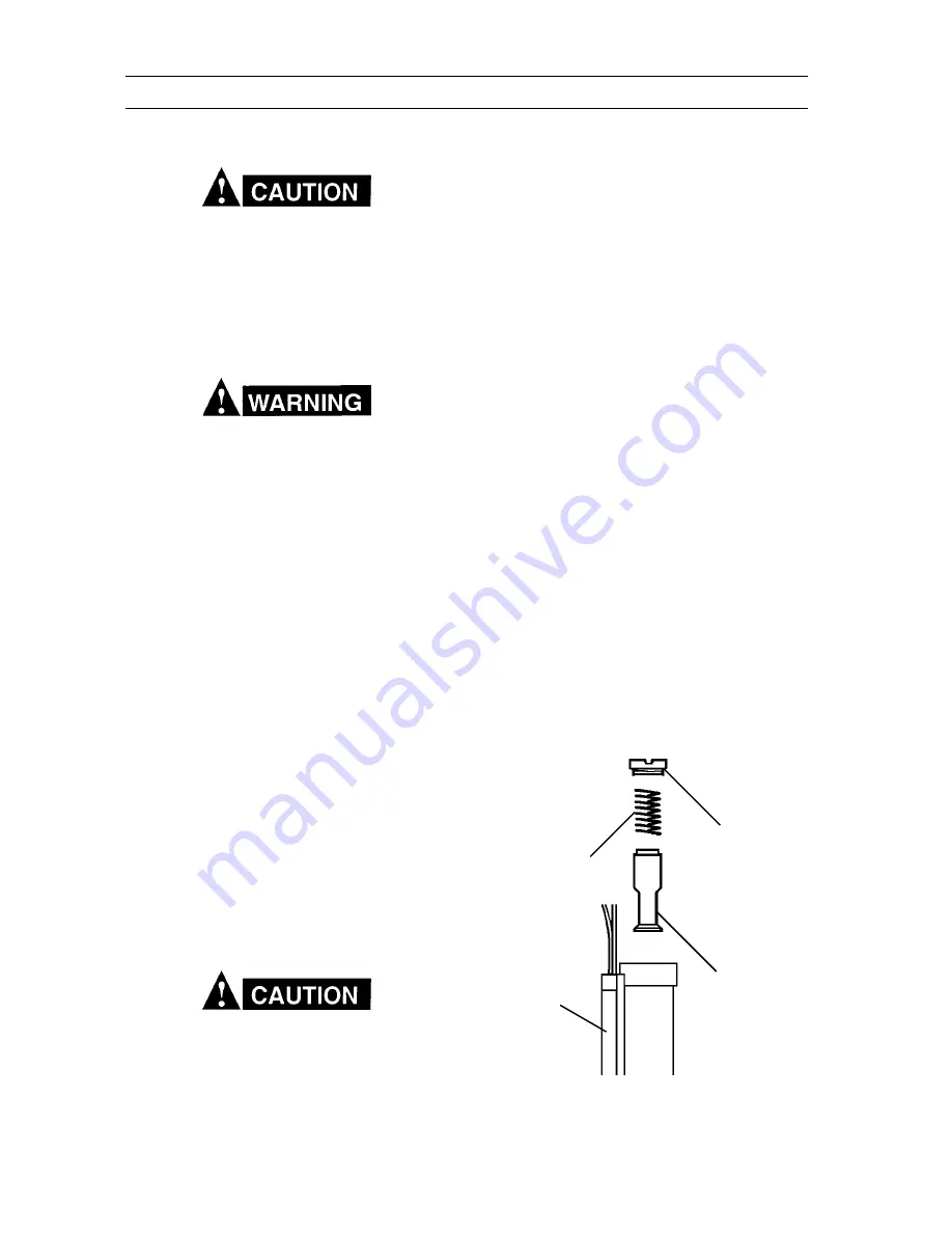
PISTON PLUG

PISTON

SPRING

FLOW SWITCH

H.

With all input power disconnected, and wear-
ing proper eye and face protection, blow out
the inside of the PowerCut-550 using low-
pressure dry compressed air.

4.3   FLOW SWITCH (FIGURE 4-1)

When excessive contamination is found in the air,
the flow switch (FS) should be removed, disas-
sembled and cleaned as follows:

A.

Ensure the system is shut down and there is no
trapped air under pressure in the piping.

B.

Remove the piston plug.

C.

Remove the spring (FS-4 only). Use care when
handling spring to prevent distortion.

D.

Remove the piston.

E.

Clean all parts with cleaning agent.

NOTE
Ensure cleaning agent does not contain sol-
vents which can degrade polysulfone. Warm
water and detergent is recommended for clean-
ing. Allow all parts to dry thoroughly before
reassembly.

Reassemble the flow switch in reverse order.

Figure 4-1. Disassembly / Assembly of Flow Switch

Summary of Contents for PowerCut-550

Page 1: ...his equipment Do NOT attempt to install or operate this equipment until you have read and fully understand these instructions If you do not fully understand these instructions contact your supplier for further information Be sure to read the Safety Precautions before installing or operating this equipment F 15 654 May 2001 This manual provides complete instructions for the following PowerCut 550 c...

Page 2: ...unction which results from improper use faulty maintenance damage improper repair or alteration by anyone other than the manu facturer or a service facility designated by the manufacturer TABLE OF CONTENTS SECTION TITLE PAGE PARAGRAPH SECTION 1 DESCRIPTION 7 1 1 General 7 1 2 Scope 7 1 3 Packages Available 7 1 4 Specifications 8 9 SECTION 2 INSTALLATION 10 2 1 General 10 2 2 Equipment Required 10 ...

Page 3: ... substances on the workpiece which might produce flammable or toxic vapors Do not do hot work on closed containers They may explode 4 Have fire extinguishing equipment handy for instant use such as a garden hose water pail sand bucket or portable fire extinguisher Be sure you are trained in its use SAFETY PRECAUTIONS 10 98 5 Do not use equipment beyond its ratings For example overloaded welding ca...

Page 4: ...ders away from heat sparks and flames Never strike an arc on a cylinder 5 For additional information refer to CGA Standard P 1 Precautions for Safe Handling of Compressed Gases in Cylinders which is available from Com pressed Gas Association 1235 Jefferson Davis High way Arlington VA 22202 EQUIPMENT MAINTENANCE Faulty or improperly maintained equipment can cause injury or death Therefore 1 Always ...

Page 5: ...ais le câble Utilisez toujours un équipement correctement entretenu PRÉCAUTIONS DE SÉCURITÉ AVERTISSEMENT Ces règles de sécurité ont pour objet d assurer votre protection Veillez à lire et à observer les précautions énoncées ci dessous avant de monter l équipement ou de commercer à l utiliser Tout défaut d observation de ces précautions risque d entraîner des blessures graves ou mortelles 1 PROTEC...

Page 6: ...ticulières en matière de ventilation indiquées à l alinéa 6 de la norme Z49 1 de l AWS 5 ENTRETIEN DE L ÉQUIPEMENT Un équipement entretenu de façon défectueuse ou inadéquate risque non seulement de réaliser un travail de mauvaise qualité mais chose plus grave encore d entraîner des dommages corporels graves voire mortels en déclenchant des incendies ou des chocs électriques Observez par conséquent...

Page 7: ...scriptions of the PowerCut 550 packages available as well as performance specifications Do not use any torch with this power source other than the ESAB brand PT 31XL torch Serious injury may occur if used with any other torch 1 2 SCOPE The purpose of this manual is to provide the operator with all the information required to install and operate the PowerCut 550 plasma arc cutting package Technical...

Page 8: ...Number Quantity Spare Parts Kit P N 21980 includes 35 40 A Nozzle 21008 3 Electrode 20862 2 Swirl Baffle 20463 1 Heat Shield 20282 1 NOTE PT 31XL Torch Assembly P N 21985 is supplied with the nozzle electrode swirl baffle and heat shield assembled Rated Output 40 Duty Cycle 35 A 120 V dc 60 Duty Cycle 30 A 120 V dc 100 Duty Cycle 22 A 120 V dc Output Current Range 15 to 35 Amperes Open Circuit Vol...

Page 9: ...1 2 PT 31XL Cutting Performance 2 1 4 57mm 5 1 4 133mm 75 Torch Table 1 4 PT 31XL Torch Specifications PT 31XL Torch Current Capacity 50A DCSP Shipping Wgt 2 lbs 1 kg Length of Service Lines 25 ft 7 6 m Figure 1 1 PT 31XL Dimensions ...

Page 10: ...at each step in this section be studied carefully and followed as closely as possible 2 2 EQUIPMENT REQUIRED A source of clean prefiltered dry air that supplies 250 cfh at 80 psig is required for the cutting opera tion The air supply should not exceed 150 psig the maximum inlet pressure rating of the air filter regu lator supplied with the package 2 3 LOCATION Adequate ventilation is necessary to ...

Page 11: ...e workpiece is connected to an approved earthgroundwithaproperlysizedgroundcable 2 6 SECONDARY OUTPUT CONNECTIONS REFER TO FIG 2 1 Torch comes factory installed These instructions are for torch replacement Before making any connections to the power source output terminals make sure that all pri mary input power to the power source is deenergized off at the main disconnect switch andthattheinputpow...

Page 12: ...H See Table 2 1 WORK CABLE SAFETY GROUND Ø PT 31XL WORK PLUG between work and power source Allow at least 10 ft 3 m RECEPTACLE P N 674540 Optional for 208 230 V 1 phase power sources Prefiltered AIR SUPPLY Customer Supplied 90 to 150 psig max See Table 2 1 and WARNING in regards to chassis ground in Section 2 5 ...

Page 13: ...13 SECTION 2 INSTALLATION GROUNDED WORK TABLE EARTH GROUND WORK CABLE BE SURE WORK IS IN GOOD CONTACT WITH TABLE WORK CABLE EARTH GROUND DO NOT ATTACH WORK CABLE TO PIECE BEING CUT FREE ...

Page 14: ...FIGURE 3 1 A PowerSwitch locatedonfrontpanel When placed in ON position the white pilot light will glow indicating control circuit is energized and the cooling fan will run B Output Current Control Adjustable from 15 to 35 amperes to suit cutting conditions C Air Check Push Button Switch When ener gized air filter regulator can be adjusted to desired pressure 55 65 psig before cutting operations A...

Page 15: ...cally after the machine cools down if the on off switch is still on Low Air Flow LED Green light will turn on during operation when the air flow is cor rect Will switch off below 15psi 1 bar On Off Switch White light will light when switched on even if the machine stopped for anyreason WillturnoffwhenswitchisinOFF position or the light bulb is defective Air Pressure Gauge Front Panel Shows air pre...

Page 16: ...When ending a cut the torch switch should be released and lifted off the workpiece just before theendofthecuttominimizedouble arcingwhich can damage the tip This is to prevent high fre quency from reigniting after cutting arc extin guishes 6 In the postflow mode the arc can be restarted immediately by depressing the torch switch The two second preflow will automatically cancel Cutting Speed Range ...

Page 17: ...able cause of each If problems are determined to be caused by the PowerCut 550 refer to the maintenance section of this manual If the problem is not corrected after referring to the maintenance section contact your ESAB representative A Insufficient Penetration 1 Cutting speed too fast 2 Damaged cutting nozzle 3 Improper air pressure B Main Arc Extinguishes Cutting speed too slow C Dross Formation...

Page 18: ... if necessary E Make sure cable and hoses are not damaged or kinked F Make sure all fittings and ground connections are tight Water or oil occasionally accumulates in com pressed air lines Be sure to direct the first blast of air away from the equipment to avoid damage to the PowerCut 550 PISTON PLUG PISTON SPRING FLOW SWITCH H With all input power disconnected and wear ing proper eye and face pro...

Page 19: ...on nect switch or circuit breaker before attempting inspection or work inside of the power source Check the problem against the symptoms in the following troubleshooting guide The remedy may be quite simple If the cause cannot be quickly located shut off the input power open up the unit and perform a simple visual inspection of all the components and wiring Check for secure terminal connections lo...

Page 20: ...onnect Is air adjusted to 55 65psi 4 5 bar Yes No Adjust Does air come on with air check switch Yes No No electrode in torch No valve pin in torch Replace electrode Check continuity of torch switch Replace valve pin OK No Replace torch switch Repair replace power source ...

Page 21: ... not shut off Does arc start when nozzle contacts work without depressing torch switch l Yes No Check for short in torch switch Does air flow even when PowerCut 550 power switch is OFF Yes No Replace Repair replace control solenoid valve PCB ...

Page 22: ...h light not energized Is switch ON Yes No Turn on switch Is plug in receptacle Yes No Insert plug Is cooling fan turning Yes No Replace On Off switch Check voltage at receptacle and input power line Yes No Check main fuses Replace On Off switch ...

Page 23: ...verheated LED turns off when unit cools down Yes No Is cooling air flowing Duty cycle exceeded 40 35 A Yes No or 100 22 A output Repair power source Repair fan F No current output Is input voltage within 10 of units input rating Yes No See D sequence above Repair replace Inverter ...

Page 24: ...s energized immediately The postflow time starts from the moment the torch switch is released 2 When the amber fault pilot light comes on cutting operation should be stopped PUSH RELEASE TORCH SWITCH OPEN CLOSE GAS SOLENOID VALVE PREFLOW FLOW SWITCH CLOSE FAULT OVERLOAD LIGHT HF CIRCUIT INVERTER CUTTING ARC CURRENT ENERGIZE 10 SEC Postflow OPEN 2 SEC ...

Page 25: ...hich the parts will be used The serial number is stamped on the unit nameplate 6 2 ORDERING ReplacementpartsmaybeorderedfromyourESAB distributor or from ESAB Welding Cutting Products Attn Customer Service Dept PO Box 100545 Ebenezer Road Florence SC 29501 0545 Be sure to indicate any special shipping instructions when ordering replacement parts Refer to the Communications Guide on back cover of th...

Page 26: ...26 SECTION 6 REPLACEMENT PARTS 12 5 4 2 17 14 3 11 7 8 16 10 9 13 6 15 ...

Page 27: ...558002756 HF PCB 6 0558002757 HF Generator 7 0558002738 Fan VR1 2 8 0558002739 Fan Grid 9 951202 Flow Switch 10 34574 Main Power Cable w Plug 10Ft 11 0558002746 EMI Filter 12 0558002747 ON OFF Switch S1 13 0558002764 Solenoid Valve Assembly 14 20080 Plasma Torch 15 0558002766 Earth Cable w Clamp 16 0558002767 Air Regulator Filter 17 0558002768 Pressure Gauge Spare Parts List PowerCut 550 ...

Page 28: ...AL SERVICE Telephone 800 ESAB 123 Fax 843 664 4452 Part Numbers Technical Applications Hours 8 00 AM to 5 00 PM EST Performance Features Technical Specifications Equipment Recommendations D LITERATURE REQUESTS Telephone 843 664 5562 Fax 843 664 5548 Hours 7 30 AM to 4 00 PM EST E WELDING EQUIPMENT REPAIRS Telephone 843 664 4487 Fax 843 664 5557 Repair Estimates Repair Status Hours 7 30 AM to 3 30 ...

Reviews: