5 OPERATION
0463 691 001
- 26 -
© ESAB AB 2019
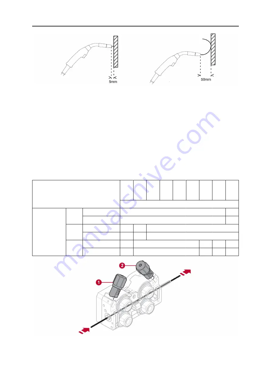
Figure A
Figure B
To check that the feed pressure is set correctly, you can feed out the wire against an
insulated object, e.g. a piece of wood.
When you hold the welding torch approx. 5 mm from the piece of wood (figure A) the feed
rollers should slip.
If you hold the welding torch approx. 50 mm from the piece of wood, the wire should be fed
out and bend (figure B).
The table below serves as a guideline showing approximate roller pressure settings for
standard conditions with correct bobbin brake force. If the torch cables are long, dirty or
worn, the pressure setting may need to be increased. Always check the roller pressure
setting on a case-by-case basis by feeding out the wire against an insulated object as
described above. A table showing approximate settings can also be found on the inside of
the left door of the wire feeder.
Wire diameter (in.)
(mm)
.023
58.3
/ 0.6
.030
58.3
/ 0.8
.040
58.3
/ 1.0
.045
58.3
/ 1.2
.052
58.3
/ 1.4
1/16
58.3
/ 1.6
.070
58.3
/ 1.8
5/64
58.3
/ 2.0
3/32
58.3
/ 2.4
Pressure setting
Wire material
Fe, Ss Tensioner unit 1
58.3 / 2.5
Tensioner unit 2
3-3.5
Cored Tensioner unit 1
2
Tensioner unit 2
2.5-3
Al
Tensioner unit 1
1
Tensioner unit 2
2-3
1.
Tensioner unit 1
2.
Tensioner unit 2


