5 OPERATION
0463 691 001
- 22 -
© ESAB AB 2019
5.5
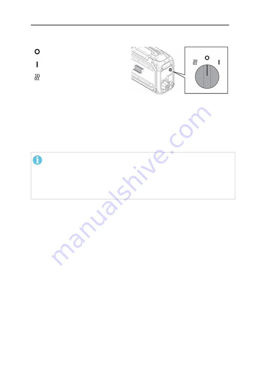
Heat kit switch (Offshore versions only)
Welding OFF
Welding ON
Heat ON and welding OFF
The bobbin area is heated to keep the
welding wire dry. Heating the bobbin
area is highly advantageous in
environments with high levels of
humidity or where the temperature
fluctuates throughout the day.
5.6
Starting procedure
When the wire feed starts, the power source generates the welding voltage. If there is no
welding current flow within three seconds, the power source switches the welding voltage off.
The wire feed continues until the welding torch's switch is switched to off.
NOTE!
It is important that the power source used together with the feeder is set to GMA
(MIG/MAG) mode when the system is powered on! This is to ensure that calibration is
made between the feeder and the power source before any welding can be done. If
the power source is set to another welding method at power on, the voltage settings
on the feeder panel
cannot
be guaranteed! If this happens, switch off the power
source, set the mode switch to GMA (MIG/MAG) and restart the power source again!
5.7
Lighting inside the wire feed unit
Lights are fitted inside the cabinet of the wire feed unit. The lights automatically switch on
when the feeder is started, when any of the parameters on the internal control panel are
changed, when wire inching is performed and after welding tasks. The lights automatically
switch off after a few minutes.
5.8
Bobbin brake
The bobbin brake force should be increased just enough to prevent wire feed overrun. The
actual brake force required depends on the wire feed speed and the size and weight of the
bobbin spool.
Do not overload the bobbin brake. If the brake force is too high, it may overload the motor,
resulting in a lower-quality welding result.
The bobbin brake force is adjusted using the 6-mm hexagon Allen screw in the middle of the
brake hub nut.


