background image

4 OPERATION

0463 697 001

- 12 -

© ESAB AB 2021

4.4

Grinding

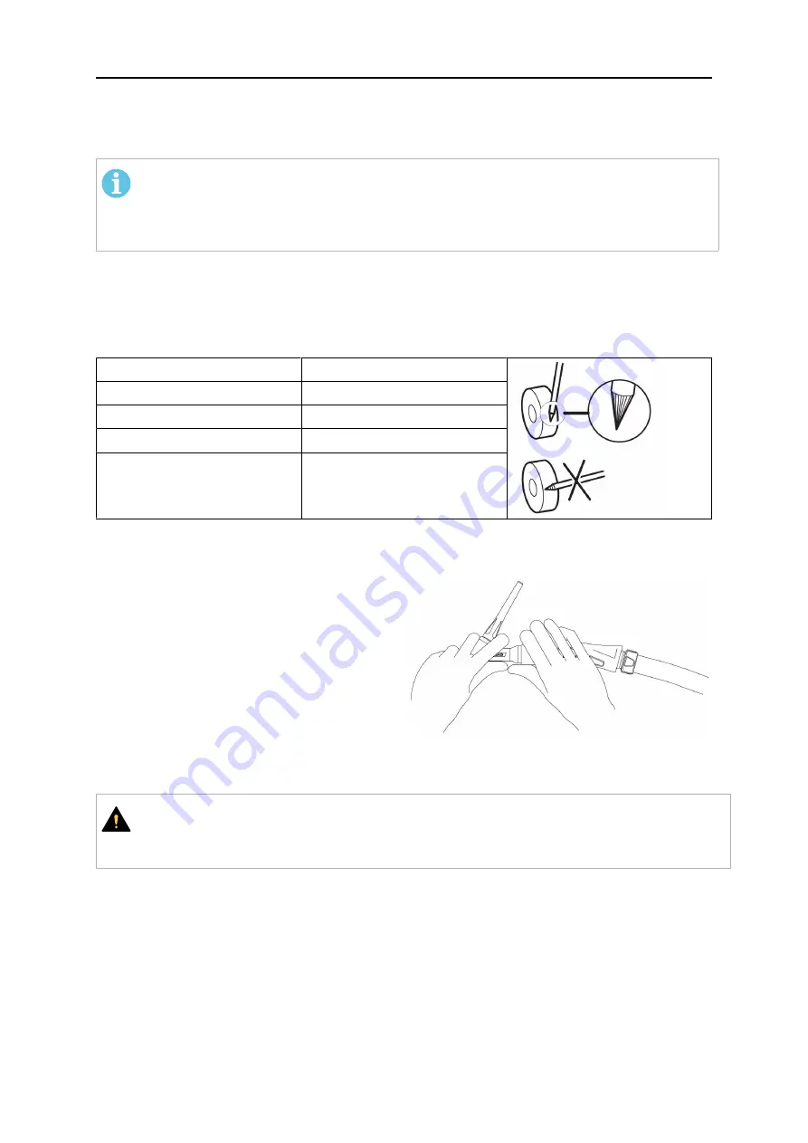
Grind tungsten electrodes according to the following table:

NOTE!

Tungsten electrodes must be grounded lengthways. If they are incorrectly grounded,
the arc may be unstable. When the welding current is increased, the angle must
also be increased.

When welding with alternating current (AC), the electrode end must be gently rounded.
Grinding the electrode is then unnecessary. Light grading of the edge is sufficient. The
electrode forms itself if it is carefully overloaded. If the tip becomes ball shaped while welding
using alternating current, this is a sign that the current is too high for the diameter of
electrode being used.

Welding current

Electrode angle

20 A

30°

20–100 A

30°–90°

100–200 A

90°–120°

over 200 A

120°

4.5

Bending of the flexible torch

The life of the flexible torch is limited. The
maximum bending angle should be
45 degrees.

The life of the torch head can be prolonged by
proper technique.

Always make sure that the torch head is
supported by the thumb when you bend. This
prevents damages at sharp bendings.

4.6

Valve torches

CAUTION!

Do not operate TIG torches with an integrated valve in the torch neck on welding
systems equipped with an ignition and stabilization device.

Summary of Contents for SR-B 17

Page 1: ...Instruction manual 0GGCAGH ccgjgc 0463 697 001 GB 20210113 SR B 9 SR B 17 SR B 26 SR B 26 HD SR B 18 SR B 20 SR B 21 SR B 400 XCT B 400W ...

Page 2: ......

Page 3: ...ERATION 11 4 1 General 11 4 2 Connections 11 4 3 Choice of electrode 11 4 4 Grinding 12 4 5 Bending of the flexible torch 12 4 6 Valve torches 12 5 MAINTENANCE 13 5 1 Daily 13 6 TROUBLESHOOTING 14 7 ORDERING SPARE PARTS 15 ORDERING NUMBERS 16 WEAR PARTS 18 Rights reserved to alter specifications without notice ...

Page 4: ...t the requirements that apply to this type of equipment The following recommendations should be observed in addition to the standard regulations that apply to the workplace All work must be carried out by trained personnel well acquainted with the operation of the equipment Incorrect operation of the equipment may lead to hazardous situations which can result in injury to the operator and damage t...

Page 5: ... ELECTRIC AND MAGNETIC FIELDS Can be dangerous to health Welders having pacemakers should consult their physician before welding EMF may interfere with some pacemakers Exposure to EMF may have other health effects which are unknown Welders should use the following procedures to minimize exposure to EMF Route the electrode and work cables together on the same side of your body Secure them with tape...

Page 6: ...closed containers HOT SURFACE Parts can burn Do not touch parts bare handed Allow cooling period before working on equipment To handle hot parts use proper tools and or insulated welding gloves to prevent burns MALFUNCTION Call for expert assistance in the event of malfunction PROTECT YOURSELF AND OTHERS CAUTION This product is solely intended for arc welding WARNING Do not use the power source fo...

Page 7: ...d or electronic equipment that has reached the end of its life must be disposed of at a recycling facility As the person responsible for the equipment it is your responsibility to obtain information on approved collection stations For further information contact the nearest ESAB dealer ESAB has an assortment of welding accessories and personal protection equipment for purchase For ordering informa...

Page 8: ...n models are available with flex heads for unlimited movement in confined spaces Accessories for the product can be found in the ACCESSORIES chapter of this manual The TIG torch is supplied with wear parts except electrodes Ø 1 6 mm 0 063 in SR B 9 Ø 2 4 mm 0 094 in SR B 17 Ø 2 4 mm 0 094 in SR B 26 Ø 2 4 mm 0 094 in SR B 26 HD Ø 2 4 mm 0 094 in SR B 20 Ø 2 4 mm 0 094 in SR B 21 Ø 2 4 mm 0 094 in ...

Page 9: ...40 60 140 60 200 60 0 5 1 6 mm 0 02 0 063 in 0 5 2 4 mm 0 02 0 094 in 0 5 4 0 mm 0 02 0 157 in Ar Ar He 4 8 m 13 26 ft X X X 12 kV 113 V SR B 26 HD 26FX HD SR B 26V HD SR B 18 18FX SR B 20 20FX SR B 21 21FX SR B 400 XCT B 400W X X X X X 70 C 158 F AC A DC A 160 60 230 60 225 100 320 100 160 100 220 100 240 100 340 100 315 100 450 100 0 5 4 0 mm 0 02 0 157 in 0 5 3 2 0 02 0 126 in 1 0 4 8 0 039 0 1...

Page 10: ...2 5 kW 1 7 l min For other application parameters or longer cables refer to additional documents that may have been included with your torch CAUTION Return temperatures of more than 60 C can cause damage or destruction of the torch The cooler must always be filled with sufficient cooling liquid refer the user manual of the cooling unit In case of a high thermal load on the torch use a cooler with ...

Page 11: ...d arc stability Alloyed tungsten electrodes have a longer service life tolerate higher currents and are less likely to leave tungsten residue in the weld Pure tungsten electrode AC Green WP Used for welding light metal alloys Cerium alloyed tungsten electrode AC DC Grey WC20 Used for welding light metals such as aluminium and magnesium Electrode tip must be rounded when welding Lanthanum alloyed t...

Page 12: ...ed If the tip becomes ball shaped while welding using alternating current this is a sign that the current is too high for the diameter of electrode being used Welding current Electrode angle 20 A 30 20 100 A 30 90 100 200 A 90 120 over 200 A 120 4 5 Bending of the flexible torch The life of the flexible torch is limited The maximum bending angle should be 45 degrees The life of the torch head can ...

Page 13: ...r attempts any work to rectify any faults in the product during the warranty period 5 1 Daily Check that all cables and hoses are undamaged and that there are no kinks in them Check that the gas nozzle is free from defects and suitable for the work in question Check that the shielding gas flows evenly and without restriction Check that the electrode is undamaged and that the electrode has been gro...

Page 14: ...rrent Check the cable and contact Regrind along the length of the electrode Flush clean with gas Replace with a smaller electrode No trigger function Control cable interrupted faulty Check repair Gas shielding is poor There are impurities in the shielding gas moisture air There are impurities in the base material rust lubricant Insufficient or total lack of shielding gas It is too draughty at the ...

Page 15: ...e with the international and European standards IEC EN 60974 7 On completion of service or repair work it is the responsibility of the person s performing the work to ensure that the product still complies with the requirements of the above standard Spare parts and wear parts can be ordered through your nearest ESAB dealer see esab com When ordering please state product type serial number designat...

Page 16: ...X X X 0700025508 SR B 17 X X 0700025509 SR B 17 X X 0700025510 SR B 17 X X 0700025511 SR B 17 X X 0700025512 SR B 17V X X 0700025513 SR B 17V X X 0700025514 SR B 17V X X 0700025515 SR B 17V X X 0700025516 SR B 17FX X X X 0700025517 SR B 17FX X X X 0700025518 SR B 26 X X 0700025519 SR B 26 X X 0700025520 SR B 26 X X 0700025521 SR B 26 X X 0700025522 SR B 26V X X 0700025523 SR B 26V X X 0700025524 S...

Page 17: ...B 21FX X X X X 0700025538 SR B 400 X X X 0700025539 SR B 400 X X X 0700025540 XCT B 400W X X X 0700025541 XCT B 400W X X X 0700025542 XCT B 400W X X X 0700025543 XCT B 400W X X X 0463698001 Spare parts list Spare parts and wear parts can be ordered through your nearest ESAB dealer see esab com When ordering please state product type serial number designation and spare part number in accordance wit...

Page 18: ...C DC 0151 574 230 0151 574 231 0151 574 243 0151 574 232 0151 574 233 0151 574 234 0151 574 235 0151 574 050 0151 574 051 0151 574 246 0151 574 052 0151 574 053 0151 574 054 0151 574 055 Lanthanum 1 5 Lanthanum 1 5 Lanthanum 1 5 Lanthanum 1 5 Lanthanum 1 5 Lanthanum 1 5 Lanthanum 1 5 Ø 1 0 Ø 1 6 Ø 2 0 Ø 2 4 Ø 3 2 Ø 4 0 Ø 4 8 Gold Gold Gold Gold Gold Gold Gold WL15 WL15 WL15 WL15 WL15 WL15 WL15 AC ...

Page 19: ...rated Ø 5 0 No 3 Ø 6 4 No 4 Ø 8 0 No 5 Ø 9 5 No 6 Ø 6 5 No 4 Ø 8 0 No 5 Ø 9 5 No 6 Ø 6 5 No 4 Gas nozzle standard L 48 mm L 63 mm L 89 mm 0700 025 664 0700 025 665 0700 025 666 0700 025 667 0700 025 668 0700 025 669 0700 025 670 0700 025 671 8 Ø 6 4 No 4 Ø 8 0 No 5 Ø 9 8 No 6 Ø 11 2 No 7 Ø 12 7 No 8 Ø 16 0 No 10 Gas nozzle for gas lens L 25 5 mm 0157 121 032 0157 121 033 0157 121 034 0157 121 039 ...

Page 20: ...Ø 2 4 Ø 3 2 Gas lens Jumbo 0700 025 676 0700 025 677 0700 025 678 11 Ø 9 8 No 6 Ø 12 7 No 8 Ø 15 9 No 10 Ø 19 0 No 12 Ø 24 0 Ø 24 0 Gas nozzle for Jumbo gas lens L 48 mm L 34 mm 0157 123 088 0157 123 089 0588 000 438 0157 123 098 0588 000 437 0700 025 679 ...

Page 21: ...9 501 217 0349 501 218 0349 501 219 7 Ø 0 5 Ø 1 0 Ø 1 6 Ø 2 0 Ø 2 4 Ø 3 0 Ø 3 2 Ø 4 0 Collet standard and for gas lens 0157 123 009 0157 123 010 0157 123 011 0700 025 681 0157 123 012 0700 025 682 0157 123 013 0157 123 014 8 Ø 1 0 1 6 Ø 2 0 2 4 Ø 3 2 Collet body short 0700 025 683 0700 025 684 0700 025 685 9 Ø 1 0 1 6 Ø 2 4 Ø 3 2 Collet body with gas lens short 0700 025 686 0700 025 687 0700 025 6...

Page 22: ...157 121 039 0157 121 040 15 Ø 6 4 No 4 Ø 8 0 No 5 Ø 9 8 No 6 Ø 11 2 No 7 Ø 12 7 No 8 Ø 15 9 No 10 Ø 19 No 12 Gas nozzle standard L 47 mm 0157 123 052 0157 123 053 0157 123 054 0157 123 055 0157 123 056 0588 000 442 0588 000 441 16 Ø 6 4 No 4 Ø 8 0 No 5 Ø 9 8 No 6 Ø 11 2 No 7 Gas nozzle standard L 76 mm 0700 025 689 0700 025 690 0700 025 691 0700 025 692 17 Ø 6 4 No 4 Ø 8 0 No 5 Ø 9 8 No 6 Ø 11 2 N...

Page 23: ...ESAB AB 2021 19 Ø 9 8 No 6 Ø 12 5 No 8 Ø 15 9 No 10 Ø 19 No 12 Ø 24 Gas nozzle for gas lens large L 48 mm 0157 123 088 0157 123 089 0588 000 438 0157 123 098 0588 000 437 20 Ø 24 Gas nozzle for gas lens short L 34 mm 0700 025 679 ...

Page 24: ... 0157 123 077 0157 123 078 0157 123 079 0157 123 074 5 Ø 1 0 3 2 Ø 3 2 4 8 Collet body standard 0157 123 081 0157 123 082 6 Ø 1 0 Ø 1 6 Ø 2 4 Ø 3 2 Ø 4 0 Ø 4 8 Collet body with gas lens 0157 123 091 0157 123 092 0157 123 093 0157 123 094 0157 123 095 0157 123 075 7 Ø 6 4 No 4 Ø 8 0 No 5 Ø 9 8 No 6 Ø 11 2 No 7 Ø 12 7 No 8 Ø 17 5 Gas nozzle standard and for gas lens L 42 mm 0157 123 057 0157 123 058...

Page 25: ...WEAR PARTS 0463 697 001 25 ESAB AB 2021 ...

Page 26: ...00 025 653 3 Ø 1 6 Ø 2 4 Ø 3 2 Ø 4 0 Collet standard 0700 025 654 0700 025 655 0700 025 656 0700 025 657 4 Ø 6 4 No 4 Ø 8 0 No 5 Ø 9 8 No 6 Ø 11 2 No 7 Ø 12 7 No 8 Ø 16 0 No 10 Gas nozzle standard L 25 5 mm 0157 121 032 0157 121 033 0157 121 034 0157 121 039 0157 121 040 0700 025 698 5 Ø 6 4 No 4 Ø 8 0 No 5 Ø 9 8 No 6 Ø 11 2 No 7 Ø 16 0 No 10 Gas nozzle standard L 35 0 mm 0700 025 658 0700 025 659...

Page 27: ...WEAR PARTS 0463 697 001 27 ESAB AB 2021 ...

Page 28: ...For contact information visit esab com ESAB AB Lindholmsallén 9 Box 8004 402 77 Gothenburg Sweden Phone 46 0 31 50 90 00 http manuals esab com ...

Reviews: