background image


19

2

8

10

9

11

UP

13

12

13

LO


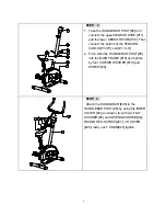
STEP    3     

1.  Take the HANDLEBAR POST [#8] and 

connect the upper SENSOR WIRE [#11] 

and the lower SENSOR WIRE [#12]. Then 

connect the bottom of the TENSION 

CABLE [#13 UP] and [# 13 LO] 

2.  Then slide the HANDLEBAR POST [#8] 

into the MAIN FRAME [#19] and tighten 

by four CURVED WASHER [#10] and 

SCREW [#9]. 

27

5 4

6

7

26

25

8

28


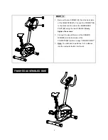
STEP  4     

Attach the HANDLEBAR [#28] to the 

HANDLEBAR POST [#8] by using the INNER 

COVER [#4] (as shown) fix with two FLAT 

WASHER [#5] and SPRING WASHER [#6], 

ROUND HEX-SCREW [#27], VH COVER 

[#26], lastly use T KNOB[#25] tighten. 

Summary of Contents for F1120

Page 1: ...G INSTRUCTIONS ESCALADE INT LTD PRODUCT CODE F1120 BLK RACING BIKE Escalade International Limited Unit 1 Viking Way Winch Wen Industrial Estate Swansea SA1 7DA Tel 01792 796893 Fax 01792 796627 Email...

Page 2: ...R YOUR RACING CYCLE IS 260 LBS 120 KGS PER USER THIS OWNER S MANUAL CONTAINS ASSEMBLY OPERATION MAINTENANCE AND SAFETY INFORMATION IN THE INTEREST OF SAFETY PLEASE MAKE CERTAIN THAT YOU READ AND UNDER...

Page 3: ...th the steps in the manual Two wrenches are included for assembly Lay out all parts on the floor Make sure that you have all the parts listed below before beginning assembly Incase of discrepancy plea...

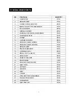
Page 4: ...WASHER 8PCS 11 TENSION CABLE UPPER 1PCS 12 TENSION CABLE LOWER 1PCS 13 SENSOR WIRE 1PCS 14 FRONT STABILIZER 1PCS 15 CARRIAGE BOLT 4PCS 16 PEDAL LEFT RIGHT 1SET 17 ACRON NUT 4PCS 18 REAR STABILIZER 1P...

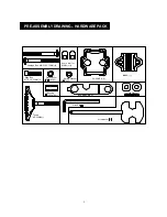
Page 5: ...for M8 Bolt 4 Flat Washer 7 12 1t 2 Allen Bolt M7 P1 0 30MM 1 T knob M7 55MM 1 Bushing 12 25MM 1 Carriage Bolt M8 P1 25 75MM 4 VH COVER 1 Curved Washer Screwdriver 1 SPANNER 1St Allen Key INNER 1 PRE...

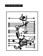
Page 6: ...6 2 11 8 10 13 12 14 15 3 4 5 6 7 16R 10 17 9 16L 18 19 20 21 22 23 24 25 26 27 28 29 52 13 UP LO EXPLODED VIEW ASSEMBLY DRAWING...

Page 7: ...r appropriate Crank Arm 47 The right crank arm is on the right hand side of the cycle as you sit on it Note that the Right pedal should be threaded on clockwise and the Left pedal on anti clockwise ST...

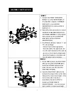
Page 8: ...the TENSION CABLE 13 UP and 13 LO 2 Then slide the HANDLEBAR POST 8 into the MAIN FRAME 19 and tighten by four CURVED WASHER 10 and SCREW 9 27 5 4 6 7 26 25 8 28 STEP 4 Attach the HANDLEBAR 28 to the...

Page 9: ...at the end of the HANDLEBAR POST 8 using the two SCREWS Firmly tighten the screws 2 Connect the plug at the end of the SENSOR WIRE 2 into the back side of the COMPUTER 1 where is says SENSOR INPUT 3 N...

Page 10: ...s the MODE ENTER button to fix your selection Please ignore the flashing word LINK Note if computer is not in use for one minute it will automatically switch off to save battery power 2 If you select...

Page 11: ...button Your program selection is now set up Press the START STOP button to start exercising Note to follow your exercise program you have to maintain the RPM value in your pedaling speed Whenever you...

Page 12: ...esents the user The bottom area represents the computer So now you are competing your speed with the computer In the center left area of the LCD it will show the computer RPM which is the value preset...

Page 13: ...select MANUAL mode press the MODE ENTER button Then set up your desired exercise time by using the UP and DOWN buttons Press the MODE ENTER button again Then press the START STOP button to start your...

Page 14: ...hile you exercise A good cool down can greatly reduce muscle cramping and muscle pain Aerobic Training Aerobic exercise during which the oxygen supply is sufficient to meet the oxygen demand of Workin...

Page 15: ...hod of exercise during which the individual performs a series of specified muscle group exercises with as little rest as possible between each muscle group Like strength training circuit training shou...

Reviews: