background image


15


Overload Alert 

The meter has provided an overload alert for voltage and current measurements. 
The beeper sounds tones periodically once the measuring value is exceeded the 
value shown as below Table 2-1: 


Table 2-1. Beeper Responses for overload Alert Points 

Measuring Function 

Start Alerting Value 

DC V 

>1000V 

AC V 

>750V 

DC + AC V 

>750V 

DC A 

>10A 

AC A 

>10A 

DC + AC A 

>10A 


If the input values over above points, the beeper still sounds tones whatever the 
beeper has been set to OFF state, or not.

Summary of Contents for 3136A

Page 1: ...E E ES S SC C CO O OR R RT T T...

Page 2: ...50000 COUNT DUAL DISPLAY MULTIMETER O Op pe er ra at ti io on na al l M Ma an nu ua al l...

Page 3: ...Front Panel Operation 3 1 Introduction 19 3 2 Front Panel Operations 19 3 3 Primary and Secondary Displays 20 3 4 Input Terminals 22 3 5 Initialization of Measurement Conditions 23 3 6 Selecting A Me...

Page 4: ...3 6 5 2 Set Commands 54 6 5 3 Query Commands 59 6 6 Remote Program Examples Using RS 232 interface 65 Section 7 GPIB Remote Operation 7 1 Introduction 71 7 2 Description of the GPIB 71 7 3 GPIB Interf...

Page 5: ...GETTING STARTED IN SECTION 2 2 BEFORE USING THE METER The meter is 50 000 count Dual Display Multi meter The meter is designed for bench top field service and system applications with a high performa...

Page 6: ...requency Measurements Up to 500KHz 0 01 Hz Resolution Resistance Measurement Up to 50 M 10m Resolutions dBm measurement with variable reference impedance from 2 to 8000 Auto or Lock Ranging Relative C...

Page 7: ...ommands and Standard Commands for Programmable Instruments SCPI The SCPI commands used in this device is conformance with the SCPI Standard Version 1993 0 Standard accessories come with the meter are...

Page 8: ...r operation and to start taking basic front panel operations and measurements quickly Section 3 Operating the Meter from the Front Panel Providing a complete description of each operation which can be...

Page 9: ...eserved for conditions and actions that pose hazard s to the user CAUTION is reserved for conditions and actions that may damage your meter WARNING TO AVOID ELECTRICAL SHOCK OR OTHER INJURY Be sure th...

Page 10: ...meter in the circuit To avoid fire hazard always use a specified fuse Use clamp on probes when measuring circuits exceeding 10 amps When servicing the meter use only the replacement parts specified D...

Page 11: ...of purchase immediately Save the container and packing material in case user has to return the meter Front Panel The front panel shown in Figure 2 1 has three main elements the input terminals on the...

Page 12: ...frequency range is at 50 60Hz For operation safety DO NOT APPLIES a line voltage that exceeds the range specified to line cord connector on the rear panel of the meter LINE VOLTAGE FUSE 16VA 50 60Hz W...

Page 13: ...igned anti slippery protective holsters on the front and rear panel sides shown in Figure 2 1 and 2 2 The holsters provide a protection to both front and rear panels of the meter as well as its corner...

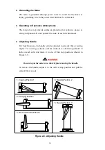
Page 14: ...andle For bench top use the handle can be adjusted to provide three viewing angles For viewing positions pull the ends out to a hard stop about 1 4 inch on each side and rotate it to one of four stop...

Page 15: ...ation status set at factory is shown in Table 3 2 2 4 Selecting Current Input Terminals and Measurement Range If current dc or ac is being measured in the Auto ranging mode with a signal input on the...

Page 16: ...ns simultaneously EXAMPLE and simultaneously to select True RMS AC volts and DC volts calculated on the primary display More detail operations are described in Section 3 2 6 Basic Measurement Examples...

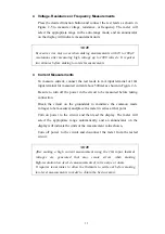
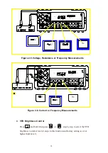
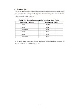
Page 17: ...shown in Figure 2 6 Be sure to turn off the power in the circuit to be measured before taking connection Break the circuit on the groundside to minimize the common mode voltage to be measured and plac...

Page 18: ...y Measurements POWER Figure 2 6 Current or Frequency Measurements VFD Brightness Control Press and hold then press or step by step to select the VFD brightness to darker level 4 steps in this function...

Page 19: ...measuring value is exceeded the value shown as below Table 2 1 Table 2 1 Beeper Responses for overload Alert Points Measuring Function Start Alerting Value DC V 1000V AC V 750V DC AC V 750V DC A 10A...

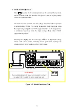
Page 20: ...a single beep tone when the input voltage drops below 0 7V approximately 1 4k and generates a continuous beep tone when the input voltage drops below 50mV approximately 100 Readings are displayed in t...

Page 21: ...er will sound if the resistance is less than 10 For other ranges the beeper will sound if the resistance falls below the typical values indicated in Table 2 2 Table 2 2 Beeper Responses in Continuity...

Page 22: ...provided with it 1 Adjusting the handle of the meter to its upward vertical stop position refer to Figure 2 3 and pull the ends all the way out 2 Removing two protective holsters out of the front pane...

Page 23: ...TO Manually select a measuring range for the primary display Select function modifier that cause the meter to display relative readings REL minimum or maximum values MIN MAX or decibels dBm and dB or...

Page 24: ...e figure 3 1 The primary display contains of larger digits and annunciators and is located on the left side of the dual display Readings using the relative REL minimum maximum MIN MAX data refresh hol...

Page 25: ...mote state REMOTE 13 Compare function COMP 14 Shift mode S 1 Auto range AUTO 2 Data Refresh Hold mode HOLD 3 Dynamic recording MIN MAX 4 Relative mode REL 5 dBm indicator dBm 6 Diode Continuity mode 7...

Page 26: ...Current Measurement 500 A 5mA 50mA 500mA Fuse Holder 1A 250V Fuse Fast Figure 3 2 Input Terminals Table 3 1 Input Protection Limits Function Input Terminal Maximum Allowable Input Vdc to COM 1200V 1...

Page 27: ...y the user Table 3 2 Default configuration Status Parameters Default Settings Function DCV Range Auto Range Remote Local Local Data Refresh Hold OFF Trigger Type Internal Compare mode HI 10000 10000E...

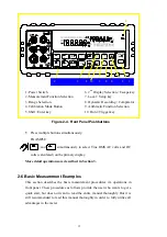
Page 28: ...2 Measurement Function Selection 7 Local Setup key 3 Range Selection 8 Dynamic Recording Comparator 4 Calibration Mode Button 9 Arithmetic Function Selection 5 Shift Enter key 10 Hold Trigger key Fig...

Page 29: ...n order to eliminate the noise interference which might be induced to the test leads it is recommended to use a shielded test cable for measuring resistance above 500K More operations of selecting a m...

Page 30: ...ge automatically when a reading is greater than full scale If no higher range is available OL overload will be displayed on primary or secondary display Likewise the meter will automatically selects a...

Page 31: ...ay Mode to turn the secondary display on and select the related function with the primary display To Disable the Secondary Display Mode cycling to turn off the secondary display see Table 3 4 Descript...

Page 32: ...he Frequency reading is corresponding to the current or voltage input signal respectively b The frequency measurement is always working on auto ranging mode The Buttons of AUTO UP and DOWN are used to...

Page 33: ...menu The original parameter is indicated in primary display or to select the parameters of the menu item The selecting parameter will be flashing once it is different to original parameter to confirm...

Page 34: ...S 232 Printer Only OFF ON or OFF Address 8 0 to 30 GPIB 1 Talk OFF ON or OFF Ref 600 8000 1200 1000 900 800 600 500 300 250 150 135 125 124 110 93 75 50 16 8 4 2 Beep ON ON or OFF Beeper Frequency 409...

Page 35: ...indicated and flashed on the secondary display within 3 seconds The default value by factory is 600 In dBm modifier mode press and to select the different impedance desired the reference impedance wil...

Page 36: ...urement reading exceeds the previous recorded reading If MIN modifier is selected the display indicates the latest minimum reading and elapsed time accordingly until next measurement reading drops bel...

Page 37: ...the displayed value This feature is useful when user wants to keep the measuring reading user may press to freeze the primary display and then read the display reading without loosing the reading Refr...

Page 38: ...ents Operation Procedures to enable Data Hold mode and the annunciator HOLD will be shown on the primary display again to disable Data Hold mode Note The Data Hold mode can be used for other arithmeti...

Page 39: ...to HI or LO and one tone from HI or LO to PASS Notes 1 The Compare function can be used with other arithmetic functions such as REL MINMAX and dBm modifiers 2 For frequency measurement it will be lock...

Page 40: ...t which digit will be adjusted Push the buttons to left shift or right shift five digits D5 D4 D3 D2 D1 D5 D4 D3 D2 D1 The UP and DOWN button is used to adjust the value press UP or down button to inc...

Page 41: ...N button again to 60000 then the setting value will be subtracted 50000 automatically Using Percentage Function To transfer the measuring value with a proportional percentage display For example trans...

Page 42: ...settling has been set by meter automatically The amount of trigger delay varies depending on different function When external trigger is enabled the meter determines the ranges for the primary displa...

Page 43: ...a measuring then the result will be indicated and held on display 3 Press to get a new value again 4 Press or to select auto ranging or manual range as necessary 5 Press other function keys to select...

Page 44: ...40 This page is subject to be blank...

Page 45: ...test and measurement capabilities Some common combinations and applications of using dual display are provided in Table 4 1 Table 4 1 Typical Combinations and Applications for Using Dual Display Prim...

Page 46: ...e supplied and its AC ripples by taking a single meter 1 to select DC voltage measurement for primary display 2 Connect the meter to the unit under test as shown below POWER 3 cycling to select AC vol...

Page 47: ...meter to the unit under test as shown below POWER WARNING 1 Select a correct input terminal according to the input range to be used 2 To avoid damaging the meter do not apply current exceeding specifi...

Page 48: ...circuit by taking a single meter 1 to select AC voltage measurement function for primary display 2 Connect the meter to the unit under test as shown below POWER 3 to select frequency measurement for...

Page 49: ...age exceeding 500 V peak between and COM input terminals 2 to select measurement 3 or to select auto ranging or manual range for primary display Note When measuring low resistance use REL modifier fun...

Page 50: ...by using the following formula AC DC RMS 2 2 ac dc Note When voltage ac dc measurement function is selected the Vdc input impedance is paralleled with an ac coupled 1 1M ac divider Measurement example...

Page 51: ...tions The meter is designed with closed case calibration capability no internal adjustment To enter calibration mode by pressing the CAL button located in the hole on the upper right position of the f...

Page 52: ...ing Range Accuracy Required Recommended Equipment DC Voltage Calibrator Range 0 to 1000VDC 0 002 Fluke 5520A or equivalent AC Voltage Calibrator Range 0 to 750V 1kHz 0 03 Fluke 5520A or equivalent 10m...

Page 53: ...e is a serial binary data interchange which operates from 300 to 9600 baud rate and the distance between any two RS 232 interfaces can be extended up to 50 feet RS 232 port of the meter is designed in...

Page 54: ...set RS 232 interface on Setup Mode To ensure the remote interface will operate appropriately user may need to configure the remote interface parameters Please refer to operation procedures of Section...

Page 55: ...at Vdc 500V measuring range Step Command Equivalent Keystroke Response 1 K1 Select Vdc function 2 K9 Select one range up 3 K9 Select one more range up 4 K9 Select one more range up 5 K9 Select one mor...

Page 56: ...and LF Line Feed Prompts When a host sends a command string to the meter through RS 232 interface the meter executes the command and returns one of the prompts as shown on Table 6 2 Table 6 2 RS 232 R...

Page 57: ...s Command Equivalent Keystroke on the front panel K1 Press Vdc key K2 Press Adc key K3 Press Vac key K4 Press Aac key K5 Press key K6 Press Diode key K7 Press Hz key K8 Press AUTO key K9 Press key K10...

Page 58: ...are used to set up the primary display measurements f for specifying measuring functions r for specifying ranges f is a necessary parameter for specifying the measuring functions f parameter is define...

Page 59: ...ay should be 0 or skip r Otherwise the secondary display will be set to auto ranging mode and return f is a necessary parameter for specifying the measuring functions f parameter is defined by a numer...

Page 60: ...0 1 2 3 4 5 6 Auto range 500 5k 50k 500k 5M 50M Adc 4 Aac 5 0 1 2 3 4 5 6 Auto range 500 A 5mA 50mA 500mA 5A 10A Diode 6 N A 1 0 1 2 3V 2 3V Hz 7 0 1 2 3 4 Auto range V ac dc 8 N A 1 0 1 2 3 4 5 Auto...

Page 61: ...ecifying the high or low limit numeric number 0 is to set low limit 1 is to set high limit s is a sign symbol for the limit can be set as or nnnnn is a five digit decimal number from 00000 to 50000 Ex...

Page 62: ...o digit decimal numeric number from 00 to 20 representing 21 different types of reference impedance Example Command string SO15 to set reference impedance at 600 nn Impedance nn Impedance nn Impedance...

Page 63: ...ption h1h2 is a two digit hex number each digit contains 4 bit binary codes Bit 7 4 and Bit 3 0 respectively to represent eight types of status about the meter h1 and h2 representations are described...

Page 64: ...meter operation Example If h1h2 contains a character string 18 convert it to an 8 bit binary code 00011000 that means the meter is under Auto ranging for Primary Display 1 st Auto Ranging and the read...

Page 65: ...dicates the status for other functions of meter operation Example If s1s2 contains a character string 08 convert it to an 8 bit binary code 00001000 that means the meter is under TRIG mode s1s2 Bit St...

Page 66: ...V 750V 2 N A 1 1 2 3 4 5 6 500 5k 50k 500k 5M 50M Adc 4 Aac 5 1 2 3 4 5 6 500 A 5mA 50mA 500mA 5A 10A Diode 6 N A 1 1 2 3V Hz 7 1 2 3 4 500Hz 5kHz 50kHz 500kHz V ac dc 8 N A 1 1 2 3 4 5 500mV 5V 50V 5...

Page 67: ...eset the meter to its power up initialization status without shutting down the line power It is useful to refresh the meter in warm start Recommend waiting 4 seconds to run the next command RV command...

Page 68: ...0 DC AC AC DC Current 10A 10 000E 0 500 500 00E 0 5K 5 0000E 3 50K 50 000E 3 500K 500 00E 3 5M 5 0000E 6 Resistance 50M 50 000E 6 500Hz 500 00E 0 5KHz 5 0000E 3 50KHz 50 000E 3 Frequency 500KHz 500 0...

Page 69: ...DSR signals CMD RST Reset the meter PRINT 1 CMD Send command to the meter TKECHO Waiting and checking if the command is executed successfully TKECHO Waiting to make sure the meter is in power on init...

Page 70: ...alue to main program END FUNCTION SUB TKECHO LINE INPUT 1 PROMPT Get a string from COM1 Check if PROMPT LF PROMPT RIGHT PROMPT 2 Discard LF IF PROMPT AND PROMPT THEN If not successful then LOCATE 24 1...

Page 71: ...e the meter is in power on initial state send_buffer S101 015 n Send S101 to meter tkecho 015 n Waiting and checking if the command is executed successfully send_buffer S21 015 n Send S21 to meter tke...

Page 72: ...unsigned int i for i 0 i 20 i send buffer i putchar buffer i if buffer i n break void tkecho char buffer Wait for a specific string unsigned int i 0 while 1 if buffer i read putchar buffer i if buffer...

Page 73: ...69 err 1 while retry 10000 if 0x20 inportb RS232 5 outportb RS232 p err 0 break char read void unsigned int retry 0 err 1 while retry 30000 if 0x01 inportb RS232 5 err 0 break return inportb RS232...

Page 74: ...70...

Page 75: ...ous bus star or linear bus network Total transmission path length is 2 meters multiplies number of devices whichever is less with a maximum of 3 meters separating any two devices Asynchronous 8 bits p...

Page 76: ...gramming commands IEEE 488 2 common commands and Standard Commands for Programmable Instruments SCPI The SCPI commands used in the meter are in conformance with the SCPI standard Version 1993 0 Common...

Page 77: ...an exponent 1 2E 2 0 1E 0 0 12E 3 9E 9 Numeric value Accepts NR1 NR2 and NR3 data types NRf Flexible numeric representation Only positive integers 100 255 16 Boolean Single ASCII encoded byte is retu...

Page 78: ...fer These status registers are discussed below and summarized in following Table Figure 7 1 shows the relationship of these registers Register Read Command Write Command Enable Register Status Byte ST...

Page 79: ...Request Service Master Summary Status Set to 1 if any enabled bit in the STB and SRE register is set to 1 otherwise set to 0 Status of MSS bit returned by STB command The meter asserts the SRQ contro...

Page 80: ...buffer are full Bit 3 DDE Device Dependent Error Incorrect input during calibration or RS 232 input buffer overflow Bit 4 EXE Execution Error Execution Error will occur beside no command error but it...

Page 81: ...E NRf Description Set the Standard Event Status Enable Register Parameter NRf 0 to 255 Example ESE 140 Enable bits 2 QYE 3 DDE and 7 PON and disable all the other bits ESE Description Query the Standa...

Page 82: ...f Description Set the Service Request Enable Register bits Parameter NRf 0 to 255 The bit 6 of value and unused bits are ignored when set the register Example SRE 48 Enable bits 4 MAV and 5 ESB in the...

Page 83: ...not any action on the meter SCPI approved INITiate Subsystem INITiate IMMediate Description This command is defined in the SCPI standard It will initialize the meter but not affect the settings in the...

Page 84: ...2 Set the secondary display to AC voltage CONF VOLT ACDC 0 5 1 Set the primary display to AC DC voltage and 500mV range CONFigure SCALar CURRent DC numeric value 1 2 AC numeric value 1 2 ACDC numeric...

Page 85: ...tion Set the primary display to 2 wire resistance measurement The numeric value parameter is used to configure the measuring range Parameter numeric value Measuring range 500 5000 5E 4 5E 5 5E 6 5E 7...

Page 86: ...1 OFF 0 CONFigure SCALar RANGe AUTO 1 2 Description Query the auto ranging status Response 1 Enable or 0 Disable CONFigure SCALar RANGe DIRection UP DOWN 1 2 Description Change measuring range to incr...

Page 87: ...DC Voltage 1000V 1000 500mV 0 5 5V 5 50V 50 500V 500 AC AC DC Voltage 750V 750 500 A 5E 4 5mA 5E 3 50mA 0 05 500mA 0 5 5A 5 DC AC AC DC Current 10A 10 500 500 5K 5000 50K 5E 4 500K 5E 5 5M 5E 6 Resis...

Page 88: ...eference Description Set dBm reference impedance Parameter reference The allowed value are 2 4 8 16 50 75 93 110 124 125 135 150 250 300 500 600 800 900 1000 1200 8000 ohms Example CALC DBM IMP 1000 S...

Page 89: ...or to show current reading Example CALC REC MAX Set the meter to maximum recording mode CALC REC MIN Set the meter to minimum recording mode CALC REC MINMAX Set the meter to show current reading CALC...

Page 90: ...to trigger a measurement and then output it Response Numeric data transferred as ASCII byte in NR3 format Example MEAS Meter returns the value shown on the primary display SYSTem Subsystem SCPI appro...

Page 91: ...ith the continuity test FREQuency 1 2 New Set the meter to frequency measurement FUNCtion 1 2 New Query the measuring function OFFDual New Turn off the 2ND display OFFRecord New Turn off the dynamic r...

Page 92: ...TAT Boolean New MODE New Query the calculation function INITiate IMMediate Std Reset meter without changing setup CONTinuous Boolean Std Set the meter at free run or data hold operation mode CONTinuou...

Page 93: ...ONL is called from the main body of the program or from the two subroutines GPIBERR and DVMERR When the second parameter of the function IBONL is zero the software and hardware are disabled Execution...

Page 94: ...1 TO 10 Request the measurement by sending the instruction READ If the error bit EERR is set in IBSTA call GPIBERR with an error message wrt READ CALL ibwrt dvm wrt IF ibsta AND EERR THEN CALL gpiber...

Page 95: ...led by printing an error message The status variable IBSTA will also be printed in hexadecimal along with the mnemonic meaning of the bit position The status variable IBERR will be printed in decimal...

Page 96: ...PRINT EADR Address error IF iberr EARG THEN PRINT EARG Invalid argument IF iberr ESAC THEN PRINT ESAC Not Sys Ctrlr IF iberr EABO THEN PRINT EABO Op aborted IF iberr ENEB THEN PRINT ENEB No GPIB boar...

Page 97: ...fied under single display mode in operation only Display Counts and Reading Rates Full Scale Display Counts 51 000 Counts Reading Rate Approx Measuring Function Readings Sec Measuring Function Reading...

Page 98: ...2 Input Impedance is in paralleled with capacitance 100pF Maximum input voltage 1200Vdc or peak ac on any range Response Time Approximately 1 0 second when the displayed reading reaches 99 9 dc value...

Page 99: ...Hz product on any range normal mode input 1x10⁶ V Hz product on any range common mode input Input Impedance 1M in parallel with capacitance 100pF Response Time Approximately 1 5 seconds when the displ...

Page 100: ...e Response Time Approximately 1 5 seconds when the displayed reading reaches 99 9 ac rms value of the tested input signal at the same range AC Voltage True RMS AC DC Coupling Resolution Full Scale Rea...

Page 101: ...Response Time Approximately 1 5 seconds when the displayed reading reaches 99 9 ac rms value of the tested input signal at the same range Resistance Continuity Resolution Full Scale Reading Test Readi...

Page 102: ...z 5Hz 500Hz 0 01 Hz 510 00 0 01 5 5kHz 500Hz 5kHz 0 1 Hz 5 1000 0 01 3 50kHz 5 KHz 50 kHz 1 Hz 51 000 0 01 3 500kHz 50kHz 500 kHz 10 Hz 999 99 0 01 3 Response Time Approximate 1 second when the displa...

Page 103: ...00V 25mV 500mV 500mV 5V 5V 50V 50V 500V 29 82 3 80 3 80 16 20 16 20 36 20 36 20 56 20 0 3 0 2 0 2 0 2 5 0 3 0 2 0 2 0 2 0 7 0 5 0 5 0 5 5 1000V dc 750V ac 500V 1000V 500V 750V 56 20 62 22 56 20 59 72...

Page 104: ...e measurement Common Mode Voltage 1000V dc or peak ac rms maximum between any input and earth ground Dimension Approx 255 w x 105 h x 305 d mm with holsters Weight 3 0kgs Line Voltage 100V 120V 220V 2...

Page 105: ...e sure the instrument is dried completely before using B 3 Configure the Line Voltage Caution Before setting the line voltage selector the main power should be turned off and remove Power cord from th...

Page 106: ...clip 62 25037 1U Fuse 25A 250V Fast Blow 6 31mm Table B 1 AC Power Cord and Line Fuses Selection Country and Area Outline P N Description 30 25634 1 AC Power Cord 120V 60Hz Taiwan America Japan Canada...

Page 107: ...P N 91 25195 1A Printed in Taiwan...

Page 108: ...tal Multi meters Digital Clamp ON Meters Multi display Multi meters Digital Thermometers Process Calibrators Digital L C R meters Automotive Multi meters Sweep Function Generators Frequency Counters P...

Reviews: