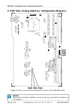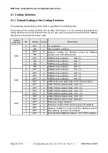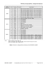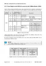
PCB View, Coding Switches, Configuration Resistors
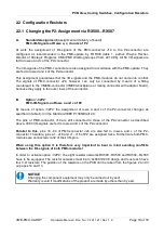
2.2 Configuration Resistors
2.2.1 Changing the P2-Assignment via RX500...RX507
A.
Standard Assignment
(assignment at delivery of board)
PMC-I/O-Signals at Rows a, c, d and z of P2
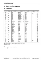
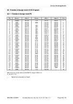
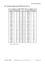
At work the assignment of I/O-signals of the PMC-connector J14 to the P2-connector are
configured as recommended in the PMC-update by FORCE (table 1, author: Wayne Fischer,
Director of Strategic Programs CMC/PMC Working Groups Chair, 22.10.96). All 64 I/O-signals are
fed to rows a and c of the P2-connector.
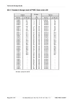
The I/O-signals of the PMC-connector are also assigned in accordance with the PMC-update. They
are fed to rows d and z of the P2-connector.
This assignment guarantees that the I/O-signals and the PMC-modules do not come into conflict.
The signals of PMC-connector J24, however, can only be connected by means of a fitting
counterpart to the VME64-connector (VME64-backplane or mating connector with adaptor board),
because they apply to the outer rows of the connector.
B.
Option ‘-32P2’
PMC-I/O-Signals on Rows a and c of P2
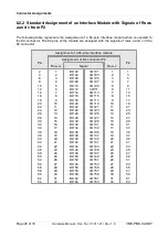
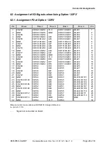
By means of option ‘-32P2’ the assignment of rows a and c of the P2-connector changes as
specified in table 6-3 in the Standard IEEE P1386/Draft 2.0:
The pins of PMC-connector J14 are still connected to those of the P2-connector as described
above. All 64 I/O-signals are fed to rows a and c of the P2-connector.
Parallel to this
, pins 33...64 of PMC-connector J24 are also fed to rows a and c of the P2-
connector. Therefore, pins a1...a16 and c1...c16 of P2 are assigned twice. Furthermore both PMC-
modules are connected via 32 of their I/O-pins.
When using this option it is therefore very important to bear in mind avoiding conflicts
between the I/O-signals of both PMC-modules!
In order to activate option ‘-32P2’, the eight resistor networks RX500...RX503 and RX504...Rx505
have to be equipped. The resistor networks must be in ‘4x0603/1206’ design and must each have
four 0-Ω resistors. The position of the resistors on the PCB can be taken from the figures 2 and 3
on pages 12 and 13.
NOTICE
Changing the component equipment may only be carried out by esd!
Warranty is void if modifications of the product are made by others than by esd.
VME-PMC-CADDY
Hardware Manual • Doc. No.: V.1911.21 / Rev. 1.9
Page 19 of 33

