WRIST STRAP TESTING WITH
MODEL 41220
This test safely checks that a
continuous path between the
operator, wrist strap and coil cord
exists.
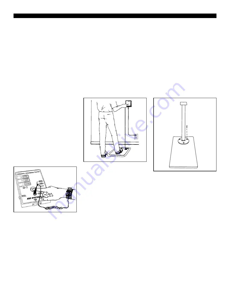
A. While wearing the wrist strap
snugly on wrist, plug the banana
plug end of the cord into the jack on
the face of the unit.
B. Switch toggle switch toward
“WRIST STRAP”.
C. Touch the test button so that the
unit activates. Hold for 2-3 seconds
while flexing coil cord area near
resistor. Audio “chirping indicates
intermittents.
Note: Often the initial
intermittency will be failure of strain
relief connection to resistor as
simulated by ESD S1.1-1998
paragraph 5.7 Bending Life Test.
Note:
DO NOT TOUCH ANY
OTHER METAL WHILE
PERFORMING TEST.
Figure 2. Testing of wrist strap
grounding assemblies.
D. Lighting of the green “PASS”
LED indicates that the wrist strap
and ground cord assemblies are
functioning properly.
E. If either “FAIL LO” or “FAIL
HI” LEDs light, the wrist strap
wearer should investigate the cause
of the failure.
TESTING FOOT GROUNDING
DEVICES WITH MODEL 41220
AND 41213 FOOTPLATE
Conductive shoes or foot grounders
should be worn on both feet. Test
each foot separately to ensure proper
operation and complete protection.
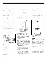
A. Place the Footplate on the floor
in front of the Multi-Range Tester.
B. Plug the plate’s ground cord into
the jack on the left hand side of the
unit.
Figure 3. Testing foot grounding
devices with the 41220/41213
C. Switch toggle switch to “FOOT
STRAP” OR “SHOE”, as
appropriate.
D. Place one foot on the plate. If the
floor is conductive, you may need to
lift the foot you are not testing off of
the floor during this test. Make sure
there is no cord plugged into the
“WRIST STRAP” jack.
E. Touch the test button so that the
unit activates. Hold down for 2-3
seconds.
F. Lighting of the green “PASS”
LED indicates that the foot ground
assemblies are functioning properly.
G. If either “Fail LO” or “Fail HI”
LEDs light, the wearer should
investigate the cause of the failure.
H. Repeat steps C through G with
other foot.
ASSEMBLY OF THE 41226
STAND
The 41226’s rugged steel pedestal
tube is powder coated in a non-
conductive white finish that helps to
prevent false readings if contacted
by skin or loose smocks.
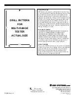
Figure 4. Attaching pedestal to
baseplate
Assembly
A. Remove 3 screws from baseplate.
B. Position pedestal on the baseplate
with the Tester mounting bracket
sloping toward the operator. Attach
pedestal to baseplate using the three
screws provided. Tighten with hex
wrench provided.
B. Attach poster to the wall at eye
level in front of the Tester location.
C. Attach ring terminal end of small
cord supplied under thumb screw.
PS-2094
Page 2 of 4
© 2005 DESCO INDUSTRIES INC.
Employee Owned


