PS-2119
Page 3 of 4
© 2007 DESCO INDUSTRIES INC.
Employee Owned
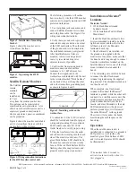
Figure 2. Installation of mounting
bracket.
Figure 3 shows the monitor as it is
viewed from the front.
Figure 3. Operating the 41222
monitor.
Satellite Remote Monitors
The Satellite
remote
monitors
can be
installed up
to 7 feet
away from the monitor control unit.
Two persons can be monitored at
separate adjacent workstations. Also
shown on each satellite remote unit is a
supervisor ground connection jack
where a supervisor, guest, or equipment
can be grounded.
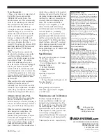
Figure 4 shows the monitor control unit
as it is viewed from the rear, with the
work surface wiring in place.
Figure 4. Wiring connection instructions
for the 41222 monitor control unit.
The following procedure will outline
how to correctly wire the 41222 monitor
control unit to properly monitor an ESD
protected workstation.
1. Use rear phone jack connections and
connect Satellite Remote Units to base
unit with phone cable. See Figure 4 for
wiring connection instructions.
2. Verify that a ground cord is properly
connected to snap socket on one corner
of the ESD worksurface. The other end
of the ground cord is to be attached to
the workbench common point ground.
After Satellite Remote Units are
mounted, route wires using a direct
route; try to avoid running wires
adjacent to metal, if possible.
3. Confirm that from ground point to
monitor connection max, surface
resistance is 1 x 10E7 ohms or less.
Connect the stripped end of the
worksurface cord included with the unit
to the terminal marked "Work Surface"
on the back of the unit. Snap the other
end to the worksurface grounding point
as shown in figures 4 and 5.
Figure 5. Installing cords on the
worksurface.
4. A convenient 3-wire 120 VAC outlet
should be located and tested for proper
wiring and grounding. We recommend
ESD Systems.com Item 41110 AC
Outlet Analyzer to verify proper wiring.
5. Plug the transformer into the outlet
and connect the mini plug into the back
side of the monitor control unit. The
green Work Surface LED should be lit.
The monitor control unit is now ready
for use. If the red Work Surface LED is
flashing, check the snap fasteners and
ground cords for proper connection.
Installation on Micastat
®
Laminate
Materials Needed:
2 15242 Flush Mount Ground
Laminate Inserts
1 15244 Installation Tool for Flush
Mount Insert
1. Install the Flush Mount Inserts first.
It is recommended to install one in the
right back corner and the other in the
left back corner of the Micastat
®
laminated bench top.
2. Once both inserts are installed, cut
the ground cord supplied with the
monitor into two pieces; make sure that
the tinned end is long enough to connect
from the worksurface terminal on the
Satellite Remote Unit to one of the flush
mount terminals located under the
bench.
3. The remaining wire can then be used
to connect the other flush mount
terminal to ground using the supplied
ring terminal. The shrouded molded end
can then be cut off.
When complete, one flush mount
terminal will connect the Micastat
®
laminate to ground, while the other will
connect it to a satellite remote unit. The
satellite remote unit then monitors the
ground connection between the two
inserts, and since Micastat
®
is the only
ESD laminate made with a physical
uniform ground layer, it will monitor
the entire Micastat
®
surface ground.
The wires will stay under the bench,
maximizing the usable space on the
bench top.
Operation
When the satellite remote unit is
installed and is connected to a grounded
ESD protective work surface, the
monitor's green Work Surfaces LED's
and its two red Operator LED’s should
be illuminated.†
ESD Systems.com • 432 Northboro Road Central • Marlboro, MA 01752 • (508) 485-7390 • Fax (508) 480-0257 • Web Site: ESDSystems.com
Monitor Release Tab
TO
POWER
ADAPTER
WORKSTATION #1
WORKSTATION #2
TO MONITOR
†The monitor takes 6 seconds to
activate its alarm circuitry when it is
first plugged in.


