PS-2063
Page 3 of 4
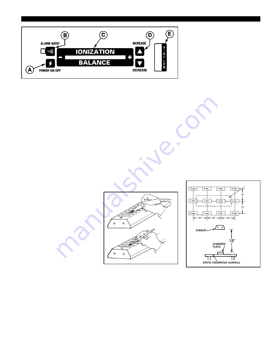
A. POWER ON/OFF:
The power
switch turns the unit off and on when
pressed. The balance and airflow
displays illuminate when the unit is
on.
B. AUDIBLE ALARM:
The audio
alarm switch allows the user to
activate or deactivate the unit's audio
alarm. A green LED will light when
the audio alarm is activated. In the
event that the unit’s ionization balance
exceeds the preset alarm limits, the
LED will turn red and begin to flash.
If the audio alarm is activated, the
visual alarm indication will be
augmented by an audible alarm. When
the unit is in the alarm mode the entire
unit will shut down with the exception
of the alarm status LED and the audio
alarm, if activated. To restart the unit,
press the POWER ON/OFF switch.
C. IONIZATION BALANCE:
During operation this LED display
provides the user with a visual
indication of the unit’s ionization
balance. When the unit is operating
within preset limits, a green LED will
be illuminated: The position of the
illuminated LED also indicates
relative balance and polarity in
relation to zero. Should the unit’s
balance shift excessively, the display
will shift to a yellow LED. Should this
condition persist continuously for
more than 20 seconds the unit will go
into the alarm mode.
D. AIRFLOW CONTROLS:
The
airflow speed controls allow the user
to quickly and easily select the most
appropriate fan speed. Fan speed is
increased by pressing on the up arrow
button and is decreased by the down
arrow button.
E. AIRFLOW DISPLAY:
The
airflow display provides a visual
indication of the relative fan speed
that has been
selected.
Maintenance
Under normal conditions the ionizer
will attract dirt and dust (especially on
the emitters and fan guards). To
maintain optimum performance,
cleaning must be done on a regular
basis. The frequency of cleaning will
depend on the environment.
Figure 11. Cleaning the emitters and
fan guards
Emitter needle cleaning is very simple
and should be done frequently.
TURN
THE IONIZER OFF.
Blow off
contaminants on the emitter
assemblies and fan guards with clean
dry air. Reset the ionizer and check
the IONIZATION BALANCE display
to verify that the unit is operating
properly.
If the ionizer does not return to proper
balance, then you may need to clean
each emitter point more thoroughly.
TURN THE UNIT OFF AND
DISCONNECT THE POWER
CORD.
With a non-linting swab or
small brush dipped in isopropyl
alcohol wipe each emitter needle
thoroughly.
Brush off emitters to assure that stray
filaments of cleaning material are
completely removed. A soft cloth and
alcohol may be used to clean each fan
guard.
Emitter Needle Replacement
The tri-metallic emitters should not
require replacement unless broken or
damaged. Replacement emitter
assemblies are available and are easy
to replace. Contact Desco for
replacement instructions and
assistance.
Neutralization Efficiency
(Decay Time)
Figure 12. Decay time in seconds from
1000 volts to 100 volts on a 6" x 6"
charged plate per ESD-S3.1
ESD
SYSTEMS
ITEM 43405
Figure 10. Control/Status Panel


