TB-5545 Page 2 of 4
Revision May 2009
© 2009 DESCO INDUSTRIES INC.
Employee Owned
ESD Systems.com • 432 Northboro Road Central • Marlboro, MA 01752 • (508) 485-7390 • Fax (508) 480-0257 • Website:
In normal factory environments, and with persons whose
capacitance with respect to ground is within design limits
(5 feet tall 90 pound person to 6 foot 5 inch 250 pound
person), the Ground Gard 3 Plus cannot be “fooled”. It
will provide a reliable alarm only when the wrist strap
becomes dysfunctional or unsafe according to accepted
industry standards. The Ground Gard 3 Plus is drift-free
and designed to be insensitive to the effects of
squeezing or stretching the coil cord.
ADVANTAGES OF WAVE DISTORTION AND
SINGLE-WIRE TECHNOLOGY
The SPI Ground Gard 3 Plus allows the use of any stan-
dard, single-wire wrist strap and coil cord. The monitor/
wrist strap/cord system life-cycle costs are by far lower
than alternative systems which require expensive & frag-
ile dual-wire cords and special wrist straps. Dual-wire
cords are expensive and are the weak link of the system,
the most likely component to need replacement. Over
a fi ve year period, this can make the dual-wire system
three to fi ve times as expensive as a system utilizing
single-wire wrist straps and cords. See Maintenance
and Calibration (page 4) to minimize life-cycle costs.
The dictionary defi nes constant as uniform and unchang-
ing, and continuous as uninterrupted. Nonetheless,
some dual-wire resistance monitors utilize a pulsed test
current and do not really provide continuous monitoring.
For example, during each 2.2 second pulse cycle of a
leading “constant” resistive monitor, electrical current is
pulsed for only 0.2 seconds followed by an unmonitored
interval of 2 seconds. This leaves the user/wrist strap un-
monitored for over 90% of each cycle. Damaging static
charges can easily occur in the portion of the time in
between the pulses. The off period of 2 seconds equals
2 billion nanoseconds, and “it takes only about 25 volts
applied for 100 nanoseconds to blow most memories or
microprocessors”.* The dual-wire system does not reli-
ably meet all industry specifi cations, as the cords do not
meet the ANSI/ESD S1.1 section 5.4
1 to 5 pound “breakaway force” requirement for operator
safety.
By using the reliable wave distortion technology to deter-
mine if the circuit is complete, there are no false alarms.
There is no need to adjust or tune the monitor to a spe-
cifi c user or installation. The miniscule amount of electri-
cal current (less than 1 volt coil cord signal) required to
generate the waveform has never caused reported skin
irritation and is extremely safe for use in voltage sensi-
tive applications such as disk drive manufacturing.
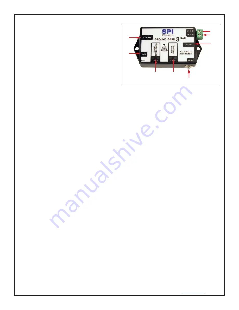
Figure 2. Ground Gard 3 Plus features and components
Features and Components
(See Figure 2)
A & D. Status LEDs:
When the green LED is lit, the
operator is properly grounded. When the red LED is lit,
the operator is either not properly grounded or not con-
nected.
B. Monitored Operator Jack:
Where the operator in-
serts the wrist cord banana plug.
C. Worksurface Ground LEDs:
When the green LED
is lit, the work surface mat is properly grounded. When
the red LED is lit, the work surface mat is not properly
grounded, or its resistance exceeds the 10 megohm
limit.
D. Operator Ground LEDs:
When the green LED is lit,
the operator is properly grounded. When the red LED
is lit, the operator is either not properly grounded or not
connected.
E. 4mm Parking Snap:
When touched by the opera-
tor, this snap will deactivate the alarm for six seconds.
This allows time for the operator to disconnect the coil
cord from the wrist band and park it on this snap. While
parked, the coil cord disables the alarm, allowing the
operator to leave the workstation. The OPERATOR
GROUND LED will remain off while the cord is parked.
Upon returning and removing the coil cord from the park-
ing snap, the operator has six seconds to hook up to the
wrist band before the alarm sounds.
F. 24 VAC Power Jack:
Connect the power adapter
here.
G. Mat Connection:
Monitors worksurface mat.
H. Mat Ground:
Grounds worksurface mat.
A
B
F
G
H
C
D
E


