TB-5545 Page 3 of 4
Revision May 2009
© 2009 DESCO INDUSTRIES INC.
Employee Owned
ESD Systems.com • 432 Northboro Road Central • Marlboro, MA 01752 • (508) 485-7390 • Fax (508) 480-0257 • Website:
Installation
Remove the monitor from its packaging and inspect for
any shipping damage. Confi rm that the work surface is 1
x 10E7 ohms or less and has a conductive layer such as
Dual Layer Rubber, Dissipative 3-Layer Vinyl, or Mica-
stat® Dissipative Laminate with conductive buried layers.
Included with each Multi-Mount Continuous Monitor
should be:
2
Mat Monitor Cords (black and green)
2
Push and Clinch Snaps
2
Mounting
screws
1
Velcro®
Set
1
120 VAC Power Adapter (
1
Certifi cate of Calibration
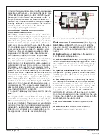
I. The Ground Gard 3 Plus may be mounted to a
convenient location using the included mounting
screws or Velcro® set. See Figure 3 for installation
set-up.
II. Install the Push and Clinch snaps 12-72 inches apart
from each other on the work surface mat. Make sure
that they pierce and clinch the bottom side of the mat.
III. Snap both ground cords to the push and clinch snaps
installed to the work surface mat.
IV. Route the black ground cord to the monitor’s green
terminal block labeled MAT.
V. Route the green ground cord to the monitor’s green
terminal block labeled GND.
VI. Connect the power adapter to the monitor’s power
jack labeled “24VAC” and the other end to a proper
voltage source.
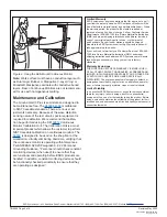
Figure 3. Installation of the Ground Gard 3 Plus
Operation
When the Multi-Mount Continuous Monitor is installed to
an ESD protective work surface and grounded via a pow-
er cord, the green WORKSURFACE GROUND LED and
red OPERATOR GROUND LED should be illuminated.
• The work surface resistance is measured between the
two snaps installed to the mat worksurface (See Figure 3).
TO USE THE CONTINUOUS MONITOR:
1. Plug a wrist strap cord, not attached to the wristband,
into the monitored banana jack labeled OPR on the side
of the unit (See Figure 2). This automatically activates
the selected operator channel. The red operator LED
should illuminate. The monitor takes 6 seconds to acti-
vate its alarm circuitry when it is fi rst plugged in.
2. Remove the charges from your body by making con-
tact with a properly grounded ESD worksurface. Snap
the cord to the wristband, and fi t it snugly onto your
wrist. This should silence the audible alarm and cause
the OPERATOR GROUND LED to switch from red to
green. If this does not happen, examine the wrist cord for
continuity or damage and your wrist band to ensure that
it is securely fi t. If you have dry skin, apply an approved
dissipative hand lotion. When leaving the area, the user
can take the wrist cord along or attach it to the monitor
parking snap. The audible alarm will shut off in approxi-
mately 6-8 seconds when operator wrist cord is removed
from unit and will instantly shut off when the cord is at-
tached to the parking snap.
PARKING SNAP
The audible alarm is designed to alert both the operator
and supervisor. The parking snap feature allows the op-
erator to disconnect when leaving the work area without
sounding the audible alarm. It also provides a means
for wrist cord storage (red OPERATOR GROUND LED
will illuminate). When the operator touches the parking
snap, the audible alarm will disable for 6 seconds. The
user can then disconnect the wrist cord from the wrist
band and attach it to the parking snap for storage. If the
operator removes the wrist cord plug from the OPR ba-
nana jack, the audible alarm will sound for 6-8 seconds.
WORK SURFACE CHANNEL
The Ground Gard 3 Plus monitoring circuitry is suffi cient-
ly sensitive to detect extremely low current when used
with a worksurface with a conductive layer.
Specifi cations:
Test range of monitored circuit 500K - 10M ohms†
Operating Voltage
120 VAC, 50/60 Hz
220 VAC, 50/60 Hz
Work Surface Range 10 Megohms (see Note)
Wrist strap open circuit voltage 1.2 volts peak to peak @
1-2 MicroAmps
Mat test open circuit voltage 5 to 7.5 volts
Response time to alarm <50 ms
Operating Temperature 0 - 40°C
Size 3.86”L x 2.10”W x .910”H
† This cannot be verifi ed with standard DC test
equipment. The continuous monitor is an impedance
sensing device and the limits are determined by the
magnitude and angle of the impedance.


