background image

Overview

1.1 Operating Modes

The operating modes "stand-alone operation" and "software-controlled operation" are available. 
They can be selected with the jumper as described in chapter '2.2 Jumper Settings'.

In all operating modes it is possible to communicate with the Hot-Swap-controller (e.g. measuring 
current/voltage).
 

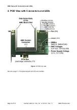
1.1.1 Stand-Alone Operation without PCIe Bus

The   power   supply   voltage   is   fed   by   an   external   power   supply   unit,   which   is   connected   via 
connector   X3.   The  AMC-PCIe-Carrier  switches   the   power   supply   voltage   through   to   the   AMC 
board and ensures the corresponding Power-Sequencing. 
The Hot-Swap functionality is exclusively executed by the hardware, the geographic address is set 
to a value which is not used by IPMI.
The current consumption can be externally determined, and the AMC board can be programmed 
via the local interfaces (e.g. serial-Debug..). 
The SMBus interface (X6) allows communication via the I²C bus.

1.1.2 Stand-Alone Operation with PCIe Bus

In this operating mode communication with the AMC board can be done via PCIe.
The power supply voltage is supplied via the PCIe interface. As described in chapter 1.2.1 after 
detecting an AMC board, the power supply voltage is supplied with short-circuit protection to the 
AMC   board.   After   detecting   the   reserved   geographic   address,   the   esd-AMC   board   starts   up 
autonomous, a communication via IPMI-IIC/SMBus is not required.  
In case if the SMBus-lines of the PCIe-Slot are not supplied, a connection from connector X6 to an 
SMBus-header and the mainboard is possible. 
 

1.1.3 Factory-Test of an AMC Board

In this operating mode the Hot-Swap cycles are controlled by a PC software. Thus it is possible to 
run systematic power-on and power-off sequences. 
The power consumption of both supply lines and the input voltages can be measured. 
Additionally the PC software can generate user-defined uTCA-Slot-IDs or start and stop the AMC 
board.
The PC-SMBus is connected to the AMC-IPMI bus. Therefore standard IPMI commands can be 
transmitted to the AMC board.  

Note!

Depending on the I²C-Controller used in the PC, request of AMC-data may not work!

The esd-AMC boards handle this situation by an extended firmware.

AMC-PCIe-Carrier

Hardware Manual • Doc. No.: U.1003.21 / Rev. 1.1

Page 7 of 16

Summary of Contents for AMC-PCIe-Carrier

Page 1: ...rds Hardware Manual to Product U 1003 01 AMC PCIe Carrier Hardware Manual Doc No U 1003 21 Rev 1 1 Page 1 of 16 esd electronic system design gmbh Vahrenwalder Str 207 30165 Hannover Germany http www e...

Page 2: ...rights to this documentation are reserved by esd Distribution to third parties and reproduction of this document in any form whole or in part are subject to esd s written approval 2013 esd electronic...

Page 3: ...below affect changes in the hardware as well as changes in the description of the facts only Revision Chapter Changes versus previous version Date 1 0 First version 2012 07 04 1 1 Title changed 2013...

Page 4: ...to electronic components To avoid this please perform the steps described on page 10 before you touch the AMC PCIe Carrier in order to discharge the static electricity from your body Qualified Persona...

Page 5: ...s 9 3 Hardware Installation 10 4 Technical Data 12 4 1 General Technical Data 12 4 2 MicroTCATM AMC Standards 12 4 3 PCI Express Interface 13 4 4 Current Measurement 13 4 5 Voltage Measurement 13 4 6...

Page 6: ...the board indicate the status of the power supply and of the Hot Swap controller For cooling of the inserted AMC boards an optional fan can be mounted at the AMC PCIe Carrier All TCA connector signals...

Page 7: ...rd can be done via PCIe The power supply voltage is supplied via the PCIe interface As described in chapter 1 2 1 after detecting an AMC board the power supply voltage is supplied with short circuit p...

Page 8: ...ith Connectors and LEDs 2 PCB View with Connectors and LEDs Figure 2 PCB top view See also page 14 for signal assignment of the connectors Page 8 of 16 Hardware Manual Doc No U 1003 21 Rev 1 1 AMC PCI...

Page 9: ...he Power LEDs 2 1 2 User LEDs LED Colour Indicator State Description LED name in schematic diagram USR1 yellow software controlled depending on software application used LED140 USR2 red LED141 The sch...

Page 10: ...mains cable but is directly connected to mains disconnect the power supply via the safety fuse and make sure that the fuse cannot switch on again unintentionally i e with caution label Danger Do not i...

Page 11: ...Hot Remove of the AMC boards Please note that common PCs do not support the Hot Insert and Hot Remove capability Please inform yourself about your PC s capability if you want to install or remove an A...

Page 12: ...e 3 3V and 12V Output X5 Phoenix SMKDSN1 5 2 SMBus connector SMCLK SMDAT X6 Dubox 3 pin Temperature range 5 C 45 C free convection Humidity max 90 non condensing Dimensions approx 111 mm x 150 mm Weig...

Page 13: ...rrent measurement 12 V Range 0 5 0 A Resolution 10 bit Accuracy 80 mA Table 6 Current measurement 4 5 Voltage Measurement Voltage measurement 3 3 V Range 0 4 V Resolution 10 bit Accuracy 40 mV Voltage...

Page 14: ...V 3 GND 4 Signal description 3 3 V 3 3 V external power supply voltage 12 V 12 V external power supply voltage GND reference potential 5 2 3 3 V and 12 V AMC Power Supply Voltage X5 Line connector Pho...

Page 15: ...e potential 12 V 12 V power supply voltage n c not connected 5 4 SMBus connector X6 Device connector DUBOX 3 pin Pin Position Pin Assignment ___ ___ ___ Signal Pin SMCLK 1 SMDAT 2 GND 3 Signal Descrip...

Page 16: ...ation PDF Manuals Manuals are available in English and usually in German as well For availability of manuals see table below Please download the manuals as PDF documents from our esd website www esd e...

Reviews: