5.1.2 Device Cabling
●
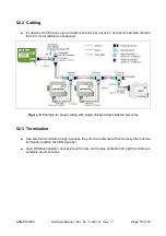
To connect CAN devices which are equipped with one CAN connector per net, use
T-connectors and cable stubs (shorter than 0.3 m).
Attention:
If single shielded
double
twisted pair cables are used, realize the T-connections by
means of connectors that support connection of two CAN cables at one connector
where the cable’s shield is looped through e.g. DSUB9 connector from ERNI
(ERBIC CAN BUS MAX, order no.:154039).
The usage of esd’s T-connector type C.1311.03 is not recommended for single
shielded
double
twisted pair cables because the shield potential of the conductive
DSUB housing is not looped through this T-connector type.
Furthermore, mixed use of single twisted and double twisted cables should be
avoided!
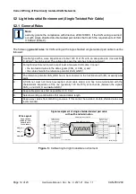
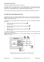
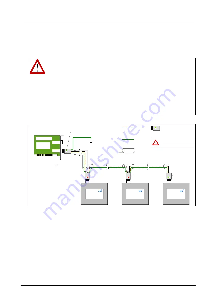
Figure. 4:
Example for proper wiring with single shielded double twisted pair cables
5.1.3 Termination
●
Use external termination plugs, because they can later be rediscovered more easily than
internal terminations within the CAN devices!
●
A 9-pin DSUB-connector with integrated switchable termination resistor can be ordered e.g.
from ERNI (ERBIC CAN BUS MAX, female contacts, order no.:154039).
CAN-PCI/200
Hardware Manual • Doc. No.: C.2021.21 / Rev. 1.1
Page 13 of 23
CAN_L
CAN_GND
CAN_H
FE
esd
CAN Modul
Shield (Abschirmung)
esd
CAN Modul
esd
CAN Modul
CAN_GND connected
to functional earth (FE)
at exactly one point
Net 2
Net 1
e.g. CPCI/405,
PMC-CAN/331,
EPPC-405, etc.
CAN-Board
termination
switched OFF
CAN T-Connector
(DSUB9 connector, female),
with switchable
termination
CAN
T-Connector
connected to earth (FE)
via computer housing
termination
switched OFF
CAN
T-Connector
CAN
T-Connector
termination
switched
ON
termination
switched
ON
Attention:
Watch for the correct position of the
termination switches at the connectors!
CAN
T-Connector


