background image

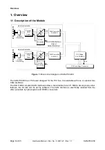
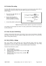
CAN Troubleshooting Guide

Normally the voltage should be between 2.0 V and 4.0 V. 

If it is lower than 2.0 V or higher than 4.0 V, it is possible that one or more nodes have faulty 
transceivers. For a voltage lower than 2.0 V please check CAN_H and CAN_L conductors for 
continuity. For a voltage higher than 4.0 V, please check for excessive voltage. 

To find the node with a faulty transceiver please test the CAN transceiver resistance (see below). 

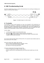
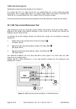
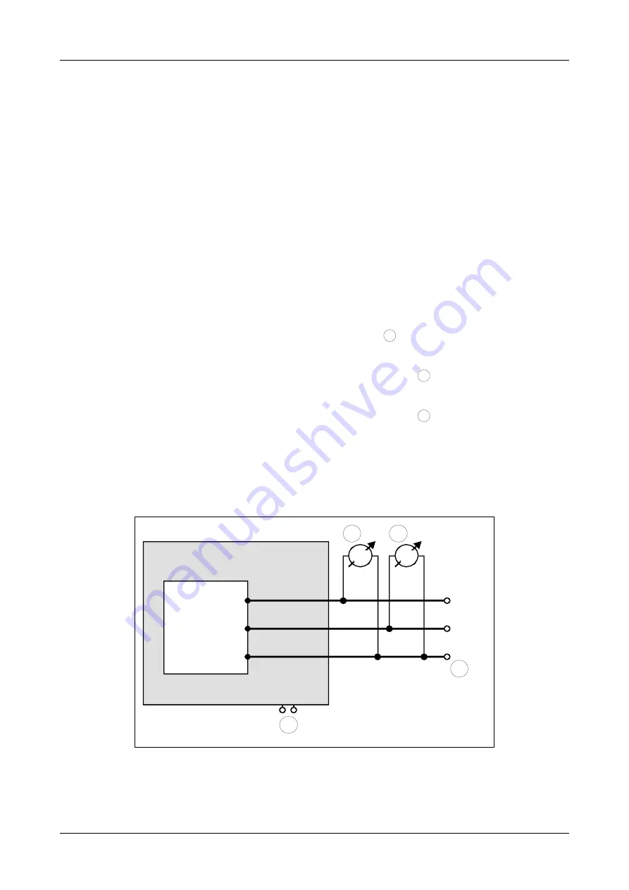
6.5 CAN Transceiver Resistance Test 

CAN transceivers have one circuit that controls CAN_H and another circuit that controls CAN_L. 
Experience has  shown  that electrical damage to one or both of  the circuits may increase the 
leakage current in these circuits. 

To measure the current leakage through the CAN circuits, please use an resistance measuring 
device and: 

1.

Switch off the node and disconnect it from the network 
(see figure below).

2.

Measure the DC resistance between CAN_H and CAN_GND 
(see figure below).

3.

Measure the DC resistance between CAN_L and CAN_GND 
(see figure below).

The measured resistance has to be about 500 kΩ for each signal. If it is much lower, the CAN 
transceiver it is probably faulty.
Another sign for a faulty transceiver is a very high deviation between the two measured input 
resistance (>> 200%). 


Figure. 9:

 Measuring the internal resistance of CAN transceivers

Page 20 of 23

Hardware Manual • Doc. No.: C.2021.21 / Rev. 1.1

CAN-PCI/200

4

5

6

CAN_H

CAN_GND

CAN_L

5

6

4

4

Power

CAN-

Transceiver

Disconnect 

Power !

Disconnect 

CAN !

CAN-node

Summary of Contents for C.2021.02

Page 1: ...21 Rev 1 1 Page 1 of 23 esd electronic system design gmbh Vahrenwalder Str 207 30165 Hannover Germany http www esd eu Phone 49 0 511 3 72 98 0 Fax 49 0 511 3 72 98 68 esd electronic system design gmbh...

Page 2: ...esd s written approval 2012 esd electronic system design gmbh Hannover esd electronic system design gmbh Vahrenwalder Str 207 30165 Hannover Germany Phone 49 511 372 98 0 Fax 49 511 372 98 68 E Mail i...

Page 3: ...Changes versus previous version Date 1 1 Added new trademarks 2012 04 13 1 1 New safety instructions 2012 03 01 1 1 1 2 New picture of the top layer 2012 03 01 1 1 2 Update chapter Hardware Installat...

Page 4: ...es may cause damage to electronic components To avoid this please perform the steps described on page 8 before you touch the CAN PCI 200 in order to discharge the static electricity from your body Qua...

Page 5: ...ion 13 5 2 Light Industrial Environment Single Twisted Pair Cable 14 5 2 1 General Rules 14 5 2 2 Cabling 15 5 2 3 Termination 15 5 3 Electrical Grounding 16 5 4 Bus Length 16 5 5 Examples for CAN Cab...

Page 6: ...be set by software The CAN interface is electrically isolated from the other potentials by optocouplers and DC DC converters Page 6 of 23 Hardware Manual Doc No C 2021 21 Rev 1 1 CAN PCI 200 5 V 5 V...

Page 7: ...1 2 PCB View with Connectors Figure 2 Top layer view of the module with 2x CAN CAN PCI 200 Hardware Manual Doc No C 2021 21 Rev 1 1 Page 7 of 23...

Page 8: ...on again unintentionally i e with caution label Danger Never carry out work while power supply voltage is switched on 4 Open the case 5 Select an open PCI slot and remove the slot cover at the back o...

Page 9: ...x 119 91 mm PCB only Weight 85 g 1 x CAN 100g 2 x CAN Table 1 General technical data of the module 3 2 PCI Bus Host Bus PCI bus according to PCI Local Bus Specification 2 1 PCI bus width 32 bit Contr...

Page 10: ...plers and DC DC converters DeviceNet Option adapter board with DeviceNet connector in Phoenix Combicon style optocouplers and CAN driver according to DeviceNet specification DeviceNet Communication Mo...

Page 11: ...reserved CAN_GND 6 2 CAN_L CAN_H 7 3 CAN_GND reserved 8 4 reserved reserved 9 5 reserved Signal Description CAN_L CAN_H CAN signal lines CAN_GND reference potential of the local CAN physical layer CA...

Page 12: ...hield to functional earth FE at least at one point 3 The reference potential CAN_GND has to be connected to the functional earth FE at exactly one point 4 A CAN bus line must not branch exception shor...

Page 13: ...le shielded double twisted pair cables 5 1 3 Termination Use external termination plugs because they can later be rediscovered more easily than internal terminations within the CAN devices A 9 pin DSU...

Page 14: ...actly one point 4 A CAN net must not branch exception short cable stubs and has to be terminated with the characteristic impedance of the line generally 120 10 at both ends between the signals CAN_L a...

Page 15: ...with single shielded single twisted pair wires 5 2 3 Termination Use external termination plugs because they can be rediscovered more easily than internal terminations within the CAN devices 9 pin DSU...

Page 16: ...delaying the CAN signals esd modules typically reach a wire length of 37 m at 1 Mbit s within a closed net without impedance disturbances like e g cable stubs 0 3 m Bit rate Kbits s Typical values of...

Page 17: ...ppflex PUR C 1x 2x 0 25 mm Order No 94 025 016 UL appr 5 5 2 Cable for Heavy Industrial Environment Applications Four Wire Manufacturer Cable Type U I LAPP GmbH Schulze Delitzsch Stra e 25 70565 Stutt...

Page 18: ...ors To test it please 1 Turn off all power supplies of the attached CAN nodes 2 Measure the DC resistance between CAN_H and CAN_L at the ends of the network see figure above and at the centre of the n...

Page 19: ...t possibly still be able to transmit data if there is a short circuit between CAN_GND and CAN_L but the error rate will increase strongly Make sure that there is no short circuit between CAN_GND and C...

Page 20: ...ircuits may increase the leakage current in these circuits To measure the current leakage through the CAN circuits please use an resistance measuring device and 1 Switch off the node and disconnect it...

Page 21: ...7 Declaration of Conformity CAN PCI 200 Hardware Manual Doc No C 2021 21 Rev 1 1 Page 21 of 23...

Page 22: ...esd CAN Hardware includes Windows XP object code J1939 Simulation Tool esd CAN Windows driver license C 1130 10 J1939 Stack for Linux J1939 Stack for esd CAN Hardware includes Linux object code esd C...

Page 23: ...le 6 Available manuals Printed Manuals If you need a printout of the manual additionally please contact our sales team sales esd eu for a quotation Printed manuals may be ordered for a fee CAN PCI 200...

Reviews: