CAN Signal Assignment of the CPCI-I/O-Connector
5. CAN Signal Assignment of the CPCI-I/O-Connector
In standard design of the module only a few GND signals are assigned to the CompactPCI I/O-
connector X101.
This design allows to use the board easily in slots whose rear-panel I/O-connectors on the
CompactPCI backplane have been designed for 64-bit accesses. Every other configuration
requires that the module is only used in slots which have been designed for I/O-signals, because
otherwise the module or other components of the CompactPCI system might be destroyed!
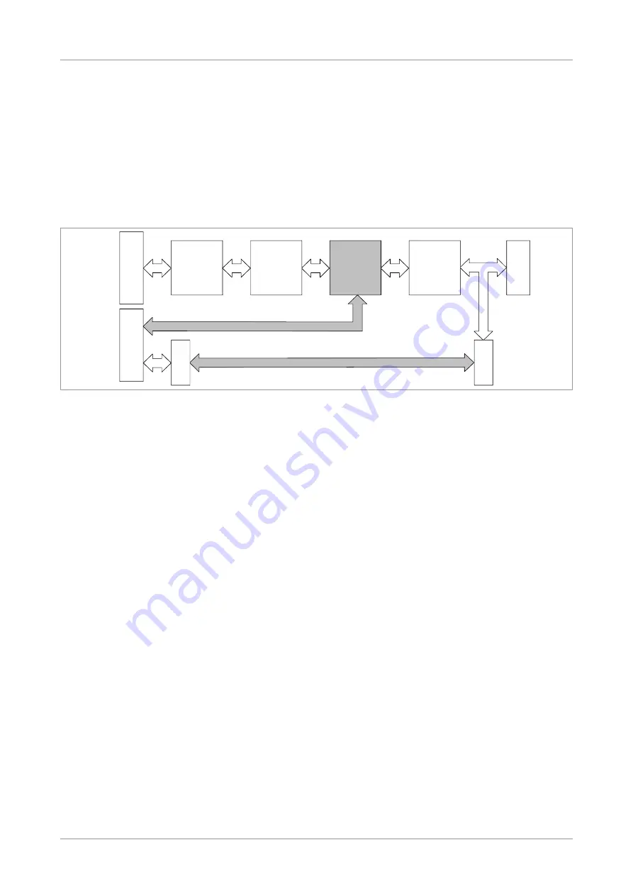
Figure 4:
Possible assignment of connector X101
(represented only in network 0)
In the following chapters the possible assignments of I/O-connector X101 will be described.
CPCI-CAN/331
Hardware Manual • Doc. No.: C.2027.21 / Rev. 2.2
Page 17 of 37
X100
CompactPCI
Board-Connector
X101
CompactPCI
Rear-Panel I/O-
Connector
CompactPCI
Interface
CAN Controller
SJA1000
Variable
Use of
Resistors
ISO11898
CAN Interface
with Electrical
Insulation
DSUB
Connector
Male connector
X400A
Male connector
X400B
Flat cable
TTL Level
TTL Level
unidirectional or differential directly from CAN controller
ISO11898-CAN signals
ISO11898-
CAN Signals


