Correct Wiring of Electrically Isolated CAN Networks
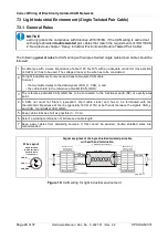
7.4 Electrical Grounding
●
For CAN devices with electrical isolation the CAN_GND must be connected between the
CAN devices.
●
CAN_GND should be connected to the earth potential (FE) at
exactly one
point of the
network.
●
Each
CAN interface with electrical connection to earth potential
acts as a grounding point.
For this reason it is recommended not to connect more than one
CAN device with electrical
connection to earth potential.
●
Grounding can be made e.g. at a termination connector (e.g. order no. C.1302.01 or
C.1301.01).
7.5 Bus Length
Bit rate
[Kbit/s]
Typical values of reachable
wire length
with esd interface
l
max
[m]
CiA recommendations
(07/95) for reachable
wire lengths l
min
[m]
1000
800
666.6
500
333.3
250
166
125
100
83,3
66.6
50
33.3
20
12.5
10
37
59
80
130
180
270
420
570
710
850
1000
1400
2000
3600
5400
7300
25
50
-
100
-
250
-
500
650
-
-
1000
-
2500
-
5000
Table 6:
Recommended cable lengths at typical bit rates (with esd-CAN interfaces)
●
Optical couplers are delaying the CAN signals. esd modules typically reach a wire length of
37 m at 1 Mbit/s within a proper terminated CAN network without impedance disturbances
like e.g. caused by cable stubs > 0.3 m.
NOTICE
Please note the recommendations of ISO 11898 regarding to the configuration of the
cable cross-section in dependance of the cable length.
Page 30 of 37
Hardware Manual • Doc. No.: C.2027.21 / Rev. 2.2
CPCI-CAN/331


