Page 8 of 31
Hardware Manual Doc.-Nr.: C.2035.21 / Rev. 2.2
CPCI-CAN/200
List of Tables
Table 1:
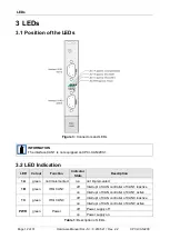
Description of LEDs ........................................................................................................ 12
Table 2:
General Data of the module ............................................................................................ 15
Table 3:
Data of the CAN interface ............................................................................................... 15
Table 4:
Data of the CompactPCI interface .................................................................................. 16
Table 5:
Recommended cable lengths at typical bit rates (with esd-CAN interfaces) .................... 24
Table 6:
Order information hardware ............................................................................................ 30
Table 7:
Order information software for CPCI-CAN/200 ............................................................... 30
Table 8:
Available Manuals .......................................................................................................... 31
List of Figures
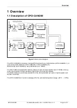
Figure 1: Block circuit diagram ........................................................................................................ 9
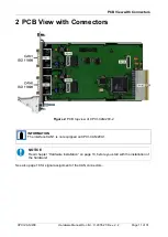
Figure 2: PCB top view of CPCI-CAN/200-2 ................................................................................. 11
Figure 3: Connectors and LEDs .................................................................................................... 12
Figure 4:
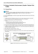
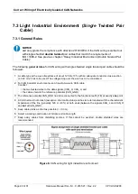
CAN wiring for heavy industrial environment ................................................................. 20
Figure 5:
Example of proper wiring with single shielded double twisted pair cables ..................... 21
Figure 6:
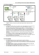
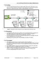
CAN wiring for light industrial environment .................................................................... 22
Figure 7:
Example for proper wiring with single shielded single twisted pair wires ........................ 23
Figure 8:
Simplified diagram of a CAN network ............................................................................ 26
Figure 9:
Simplified schematic diagram of ground test measurement ........................................... 27
Figure 10:
Measuring the internal resistance of CAN transceivers ............................................... 28


