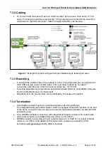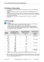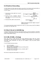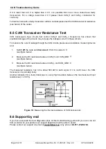
Connector Assignments
Page 18 of 31
Hardware Manual Doc.-Nr.: C.2035.21 / Rev. 2.2
CPCI-CAN/200
6 Connector Assignments
The signals are identically assigned to the connector of interface CAN0 (X301) and to the optional
interface CAN1 (X311).
Device connector:
9-pin DSUB connector, pin contacts
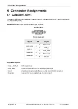
Pin Position:
Pin Assignment:
Signal
Pin
Signal
1
Reserved
CAN_GND
6
2
CAN_L
CAN_H
7
3
CAN_GND
Reserved
8
4
Reserved
Reserved
9
5
Shield
Signal Description:
CAN_L, CAN_H
CAN signal lines
CAN_GND
reference potential of the local CAN physical layer
Shield
shielding (connected with the case of the 9-pin DSUB connector)
Reserved
reserved for future applications, do not connect!
1 2 3 4 5
6 7 8 9
6.1 CAN (X301, X311)

