Hardware-Installation
Manual • Doc.-No.: C.3012.21 / Rev. 1.1 CAN-CBX-REL4
Page 14 of 99
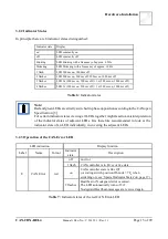
3.2 LED Display
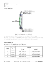
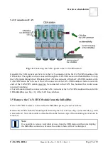
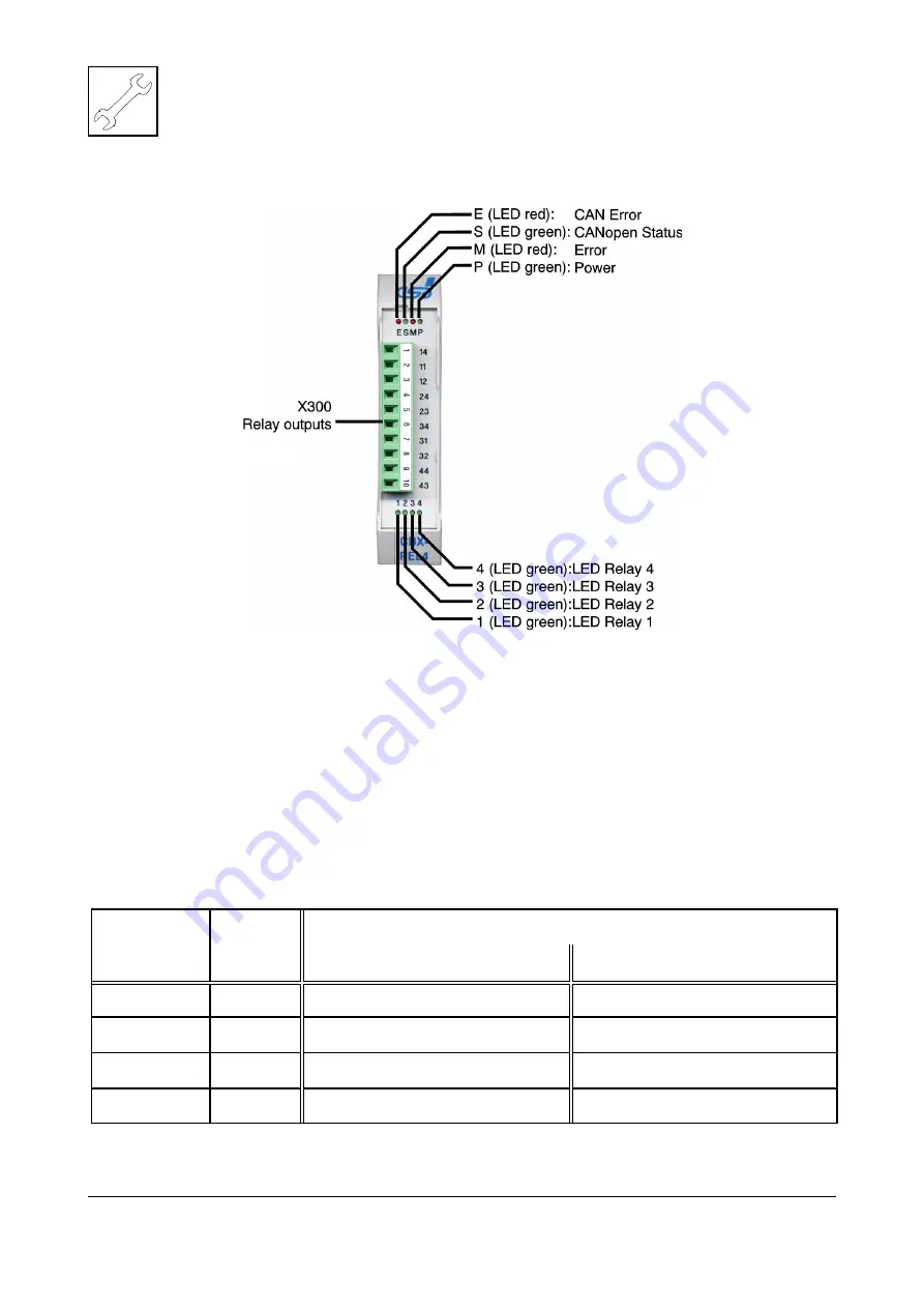
Fig. 3: Position of the LEDs in the front panel
The CAN-CBX-REL4 module is equipped with four Status LEDs and four relay LEDs.
The terms of the indicator states of the LEDs are chosen in accordance with the terms recommended
by the CiA [3]. The indicator states of the LEDs are described in the following chapters.
3.2.1 Relay LEDs 1-4
The four lower green LEDs show the states of the relays.
Label
Component
No.
Indication
LED on
LED off
1
LED300A
Relay 1 energized
Relay 1 de-energized
2
LED300B
Relay 2 energized
Relay 2 de-energized
3
LED300C
Relay 3 energized
Relay 3 de-energized
4
LED300D
Relay 4 energized
Relay 4 de-energized
Table 5: Indication of LEDs 1-4


