CAN-Bus Troubleshooting Guide
Manual • Doc.-No.: C.3012.21 / Rev. 1.1 CAN-CBX-REL4
Page 38 of 99
Ò
Ó
Ô
Õ Ö × Ø
Ù
Õ Ö × Ø
Ú
× Û
Õ Ö × Ø
Ü
Ω
Ý
Þ
ß
Ω
ß
à
á
â
ã
ä
å
æ
ç
è
é
ê
ëì
í îïð
ñï ê
òó ô
õ
ö
÷
÷
ø
õ ù
ú ö
û
ø
ü
ý
ò
ó ô
õ
ö ÷
÷ ø
õ
ù
þ
ÿ
ý
Õ Ö ×
If it is lower than 2.0 V or higher than 4.0 V, it is possible that one or more nodes have faulty
transceivers.
For a voltage lower than 2.0 V please check CAN_H and CAN_L conductors for continuity. For a
voltage higher than 4.0 V, please check for excessive voltage.
To find the node with a faulty transceiver please test the CAN transceiver resistance (see next page).
6.5 CAN Transceiver Resistance Test
CAN transceivers have one circuit that controls CAN_H and another circuit that controls CAN_L.
Experience has shown that electrical damage to one or both of the circuits may increase the leakage
current in these circuits.
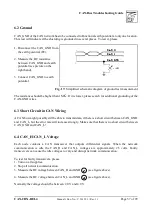
To measure the current leakage through the CAN circuits, please use an resistance measuring device
and:
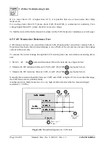
1. Switch off the
node and disconnect it from the network (see figure below).
2. Measure the DC resistance between CAN_H and CAN_GND
(see figure below).
3. Measure the DC resistance between CAN_L and CAN_GND
(see figure below).
Normally the resistance should be between 1 M
and 4 M
or higher. If it is lower than this range,
the CAN transceiver is probably faulty.
Another sign for a faulty transceiver is a very high deviation between the two measured input
resistance (>> 200%).
Figure 18: Simplified diagram of a CAN node


