Page Mode
CAN-CBM-DP
Software Manual Rev. 2.0
46
Byte:
1 2 3 4 5 6 7 8 9 10 11 12 13 14 15 16
0
17 18 19 20 21 22 23 24 25 26 27 28 29 30 31
33 34 35 36 37 38 39 40 41 42 43 44 45 46 47 48
32
49 50 51 52 53 54 55 56 57 58 59 60 61 62 63
65 66 67 68 69 70 71 72 73 74 75 76 77 78 79
64
128
159
160
191
192
209
Byte:
Byte:
81
80
Output Address:
Slot 0
Example: Page 51
(Tx-Configuration)
Page no.
Protocol Data
Parameter of Tx-Id 1
Slot 1
Slot 2
Parameter of Tx-Id 2
Parameter of Tx-Id 3
Parameter of Tx-Id 4
Parameter of Tx-Id 5
Parameter of Tx-Id 6
Parameter of Tx-Id 7
Parameter of Tx-Id 8
Parameter of Tx-Id 9
Parameter of Tx-Id 10
Page no.
Page no.
Parameter of Tx-Id 11
endconfig
Output Address:
Example: Page 51
(Tx-Configuration)
Output Address:
Example: Page 51
(Tx-Configuration)
Example 1:
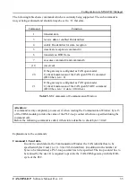
The figure above represents the assignment of a SIMATIC-S7-300 PLC for the Page Mode. 105 bytes
have been specified for the Page Mode and 16 bytes for the Communication Window. With these the
S7-300 is completely occupied, because it offers a maximum of 122 bytes.
Below the specification of a PLC-slot will be called page
segment.
In example 1 a data length of 32 bytes for each segment and the consistency for the entire 32 bytes have
been set. The data length has not been chosen larger, because the S7-300 cannot transmit more than 32
bytes consistently. This, however, is absolutely necessary for the Page Mode.
Generally a segment is to be specified with 32 bytes.
Given that at least 32 bytes have already been
specified for the input data, it is also permissible to use any length between 0 and 32 bytes for the last
segment. The length of the input data might differ from the length of the output date. It is absolutely
necessary, however, that the input addresses of successive slots are sequentially, and that the output
addresses of successive slots are sequentially.
Example 2:
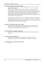
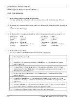
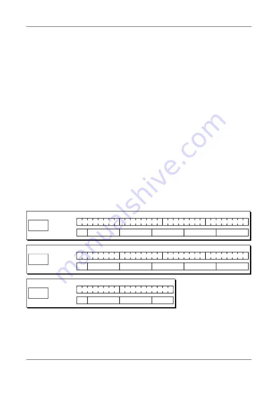
For the output page 32 bytes have been specified at slot 0 from address 128. Slot 1 has also 32 bytes
and therefore covers addresses 160...191. Slot 2 has only 18 bytes and covers addresses 192...209. A
maximum size of 82 bytes results for the output page.
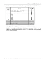
The following figure shoes the page in the address range of the PLC. For the application example the
assignment with the Tx-configuration page (page 51) has been specified. With a size of 82 bytes 11 Tx-
identifiers could be configured on one page. In the last four bytes the end identifier is specified. If more
Tx-identifiers are required, Tx-pages 52, 53, etc. are transmitted afterwards.
Fig. 6.4.4:
Example 2: Output page with a length of 82 bytes


