


Connector Assignments
2. Connector Assignments
2.1 CAN
INFORMATION
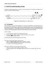
The signals of the CAN-T-Connector are connected through. The pins of the three
connectors are assigned with the same signals!
The pin assignment depends on the signals connected.
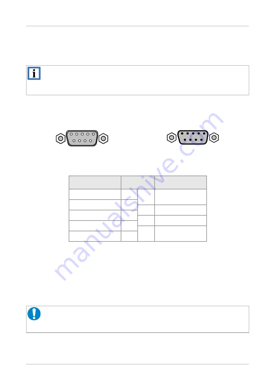
Connector: 9-pin DSUB connector 1x male and 2x female
Pin Position:
DSUB9 male:
DSUB9 female:
Example for Pin Assignment (According to CiA 303, CANopen Recommendation):
Signal
Pin
Signal
reserved
1
6
(GND)
CAN_L
2
7
CAN_H
CAN_GND
3
8
reserved
reserved
4
9
reserved
(CAN_SHLD)
5
Signal Description:
CAN_L, CAN_H
CAN signal lines
CAN_GND
Reference potential of local CAN physical layer
(CAN_SHLD)
Optional CAN shield
(GND)
Optional ground
reserved
Reserved for future applications, do not connect!
NOTICE
Note that the metal shells of the DSUB connectors are not connected. Thus, the metal
shells are not connected through the CAN-T-Connector, see Figure 3!
Read chapter “Shielding General Description” on page 9 for further information.
Page 8 of 22
Manual • Doc. No.: C.1311.21 / Rev. 1.3
CAN-T-Connector
1 2 3 4 5
6 7 8 9
1
2
3
4
5
6
7
8
9


