

All rights reserved. Reproduction as well as electronic duplication of this user guide, complete or in part, requires the written consent of
ESERA GmbH. Errors and technical modification subject to change.
ESERA GmbH, ESERA-Automation 2020
www.esera.de
11162 V2.0 R1.0 Manual
Page 2 von 5
3
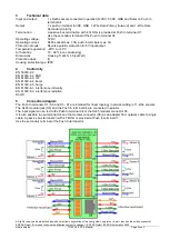
Technical data
Input and output:
1 x RJ45 sockets connected in parallel (12VDC, 5VDC, GND and Data) on Push In
terminal X4
Output:
7 x push-in terminal (5VDC, GND, 1-Wire Data Primary (forward) and 1-Wire Data
Secondary (return)
Termination:
A passive bus termination with 4.7kOhm is provided at Push In terminal X7
Use the secondary terminal of the Push In terminal X4
Operating voltage:
5VDC
Operating current:
RJ45 socket max. 1.5A, push-in terminals max. 3A
Protection circuits:
Reverse polarity protection for 5V input/output
Temperature,operation: -20°C to +60°C
Air humitidy:
10 - 92% (non condensing)
Dimensions:
Housing 112x41x 35 (LxWxH)
Protection class:
III
Housing protection type: IP00
4
Conformity
EN 50090-2-2
EN 61000-4-2, ESD
EN 61000-4-3, HF
EN 61000-4-4, Burst
EN 61000-4-5, Surge
EN 61000-6-1, interference immunity
EN 61000-6-3, interference radiation
RoHS
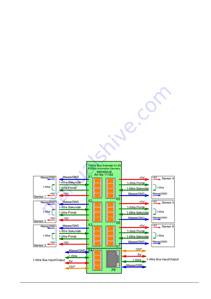
5
Connection diagram
The Push In terminals X1 - X3 and X5 - X7 are intended for linear topology (network cabling) of 1-Wire sensors.
The RJ45 modular jack (X8) and the Push In terminal X4 are connected in parallel.
The input signal can be fed to the Push In terminal X4 or the RJ45 modular connector X8.
It is also possible to use terminal X4 and the modular connector (X8) as an adapter from network cable to single
cable. A passive bus termination with 4.7kOhm is provided at Push In terminal X7
Use the secondary terminal of the Push In terminal X4.


