*if the sensor or actuator supports Auto-E-Connect. For details, please refer to the operating instructions of the sensor or actuator.
All rights reserved. Reproduction as well as electronic duplication of this user guide, complete or in part, requires the written consent of
ESERA GmbH. Errors and technical modification subject to change.
ESERA GmbH 2021
www.esera.de
11216 V5.0 R1.0 Manual
Page 4 of 9
5
Conformity
EN 50090-2-2
EN 61000-4-2, ESD
EN 61000-4-3, HF
EN 61000-4-4, Burst
EN 61000-4-5, Surge
EN 61000-6-1, Interference immunity
EN 61000-6-3, Interference radiation
RoHS
6
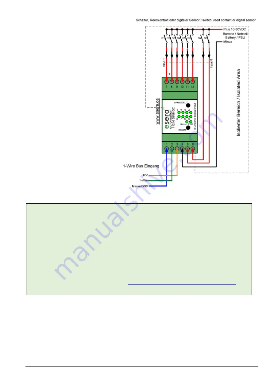
Connection diagram
The connection diagram is available in the
Shop
Connection top side:
inputs
7 = input 1
8 = input 2
9 = input 3
10 = input 4
11 = input 5
12 = input 6
6 = input 7
5 = input 8
4 = GND/ground input
Connection bottom side:
1-Wire Bus
1 = GND (1-Wire ground)
2 = 1-Wire
3 = +12V voltage
Note
The module may only be operated at the voltages and under the ambient conditions specified for it. The
operating position of the device is arbitrary.
The modules may only be commissioned by a qualified electrician.
For further information on the operating conditions, see the following instructions under "Operating
conditions".
Note on switching loads
When switching capacitive or inductive loads, very strong arcs can occur at the relay contacts, which can
cause interference with the logic of the switching module, the ECO Controller and other devices. In order to
extinguish these arcs or to dampen the resulting disturbances to such an extent, appropriate additional
circuits, such as spark quenching capacitors, and/or varistors per switching contact and free-wheeling
diodes per relay, must be provided.
For details on spark quenching, see Wikipedia:
https://de.wikipedia.org/wiki/Funkenl%C3%B6schung
The max. switching current and max. switching capacity are reduced for capacitive or inductive loads.


