Art. No. 11324
All rights reserved. Reproduction as well as electronic duplication of this user guide, complete or in part, requires the written consent of
ESERA GmbH. Errors and technical modification subject to change.
ESERA GmbH, ESERA-Automation 2020
www.esera.de
11324 V2.0 R1.0 Manual
Page 7 of 8
16
Operating conditions
The assembly may only be operated at the specified voltages and ambient conditions. The device can be
operated in any position. The device is intended for use in dry and dust-free rooms.
If condensation is formed, allow at least 2 hours for the unit to acclimatize.
The assembly can only be put into operation under the supervision of a qualified electrician. Do not operate the
module in an environment in which flammable gases, vapours or dust are present or could be present.
17
Assembly
The installation site must be protected from moisture. The device may only be used in dry indoor areas. The
device is intended for installation inside a control cabinet as a stationary device.
18
Disposal information
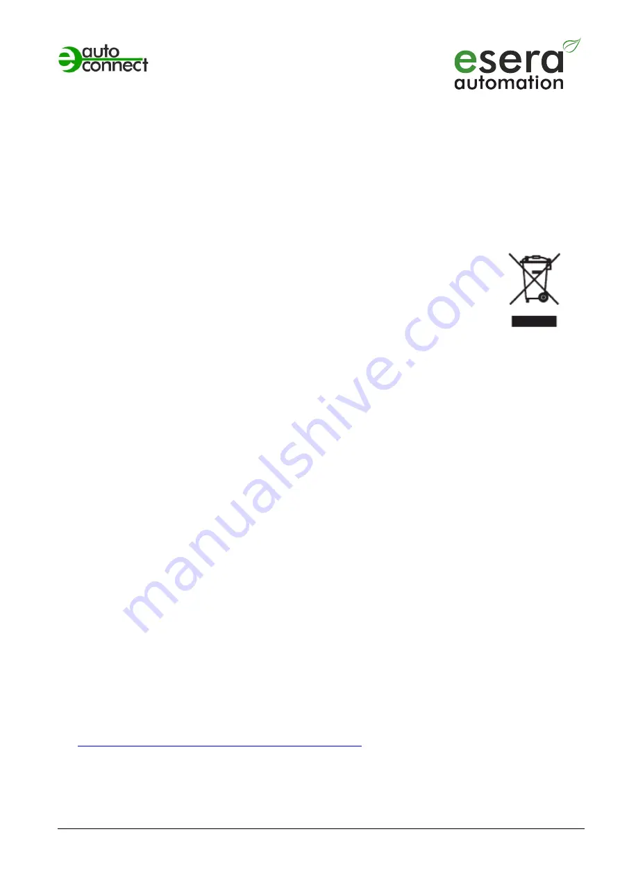
Do not dispose of the device in domestic waste! Electronic devices must be disposed of at the
local collection points for electronic waste in accordance with the Directive on Waste Electrical
and Electronic Equipment!
19
Safety Instructions
When handling products that come into contact with electrical voltage, the valid VDE regulations must be observed, in
particular VDE 0100, VDE 0550/0551, VDE 0700, VDE 0711 and VDE 0860.
When handling products that come into contact with electrical voltage, the valid VDE regulations must be observed, in
particular VDE 0100, VDE 0550/0551, VDE 0700, VDE 0711 and VDE 0860.
All termination and wiring work must only be carried out when the power is disconnected.
Before opening the device, always unplug or make sure that the unit is disconnected from the mains.
Components, modules or devices may only be put into service if they are mounted in a contact proof housing.
During installation they must not have power applied.
Tools may only be used on devices, components or assemblies if it is ensured that the devices are disconnected
from the supply voltage and that electrical charges stored in the components inside the device have been
discharged beforehand.
Live cables or wires to which the device, component or assembly is connected must always be checked for
insulation faults or breakages.
If a fault is detected in the supply line, the device must be taken out of operation immediately until the defective line
has been replaced.
When components or assemblies are used, strict compliance with the characteristics for electrical quantities
specified in the corresponding description must always be pointed out.
If it is not clear from the present description for the non-commercial end user which electrical characteristic values
apply to a component or assembly, how external wiring is to be carried out or which external components or
accessories may be connected and which connection values these external components may have, a qualified
electrician must be consulted.
Before commissioning a device, it must generally be checked whether this device or the module is basically suitable
for the application for which it is to be used.
In case of doubt, it is absolutely necessary to consult experts, experts or the manufacturer of the modules used.
We accept no liability whatsoever for operating and connection errors beyond our control.
In the event of non-function, kits should be returned with an exact description of the fault and the associated
assembly instructions without housing. A repair is not possible without a fault description. Time-consuming assembly
or disassembly of enclosures must be charged additionally.
The relevant VDE regulations must be observed during installation and when handling parts that later carry mains
voltage.
Devices which are operated at a voltage greater than 35 VDC/ 12mA may only be connected and commissioned by
qualified electricians.
Commissioning may only be carried out if the circuit is installed in a housing in a touch-proof manner.
If measurements are unavoidable when the housing is open, a safety isolating transformer must be connected
upstream or a suitable power supply unit must be used for safety reasons.
After installing the required tests according to DGUV / regulation 3 (German statutory accident
insurance,
https://en.wikipedia.org/wiki/German_Statutory_Accident_Insurance)


