28
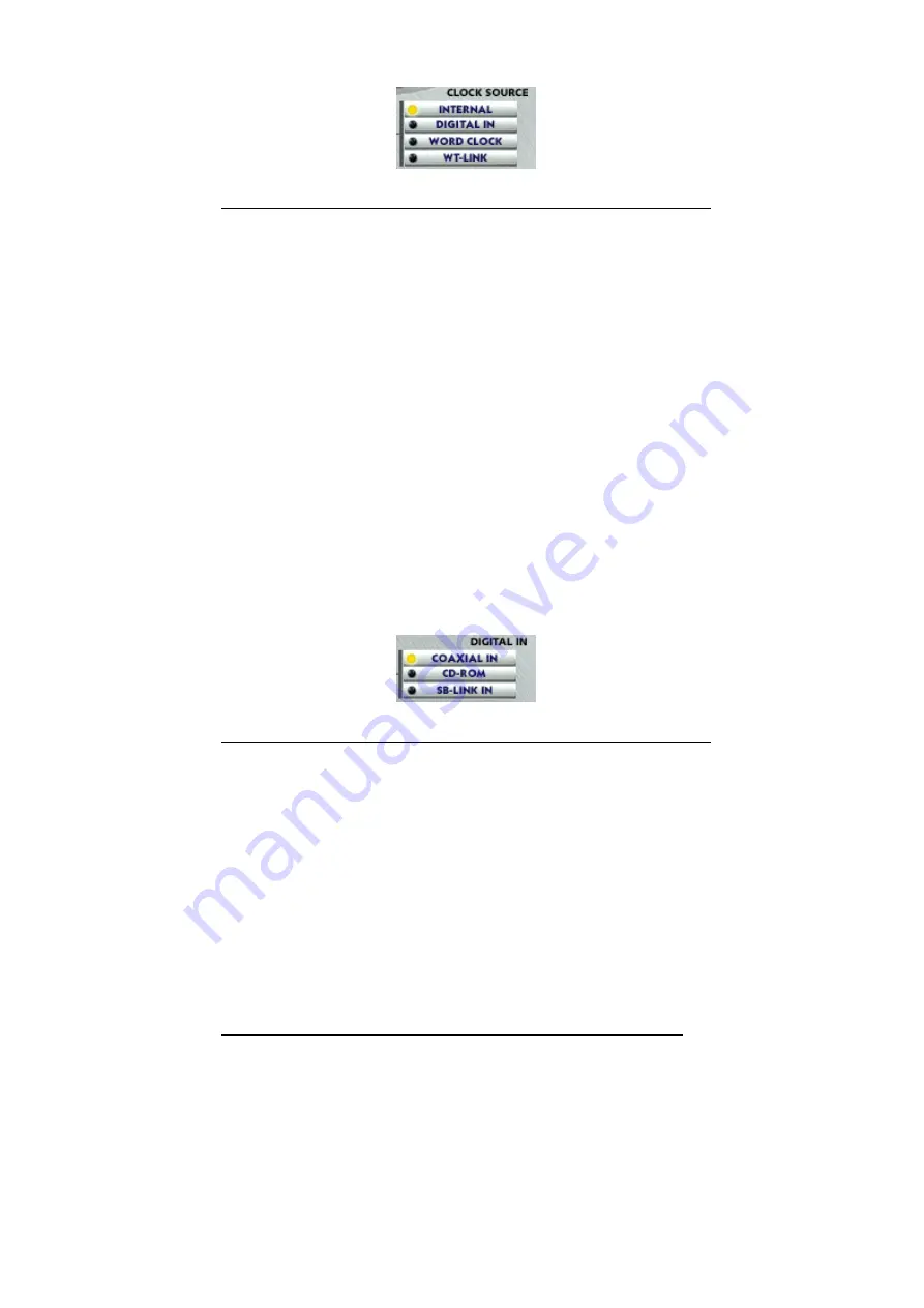
C L O C K S O U R C E
Clock source is the time reference that determines precisely where each digital audio sample
begins and ends. When you set a wrong clock source you will notice either drop-outs or you
will not get any audio output.
1. Internal
Selects the WT2496’s on-board clock source as the reference. This is the default
mode for recording analog audio through the WT2496. Use this mode if you are
running two or more digital audio or MIDI software applications simultaneously
without any external synchronization.
2. Digital
In
Selects the digital audio input’s data as the clock source. Use this mode if you are
recording digital audio through the WT2496’s digital input.
4. Word
Clock
Selects the clock source connected to the WT2496’s on-board header pin as the
reference clock.
5. WT-Link
Selects the clock source of the other EGO SYS products connected to the SYNC
IN header pin as the reference clock.
D I G I T A L I N P U T
Select the input connector type for your digital audio input.
1. Coaxial In
Selects the digital input port (RCA type S/PDIF format) on the WT2496 as the
digital input source.
2. CD-ROM
Selects the CD In 2-pin header connector on the WT2496 as the digital input
source. You must have the CD-ROM digital audio output connected to the 2-pin
header connector on the WT2496 card.
3. SB-Link
In
Selects the SB/D-In 2-pin header on the WT2496’s PCI board as the digital input
source. You must have the SoundBlaster Live Value card’s digital audio output
connected to the 2-pin header connector on the WT2496 card.

