Type / No.
Rev.
Date
Page
Total pages
EW082.695_en
5
02 August 2010
11
28
EsiWelma
s.r.l.
4
USING THE TERMINAL UNIT
After the wiring and connections between the sensor and the TUS40-20 terminal unit are
complete, visually inspect them to make sure they are correct, ensure you are operating in a
safe zone, then power up the sensor.
4.1
Operating modes
Only connect and disconnect the TUS40-20 junction box to and from the sensor if the
sensor power is off, to avoid connection errors. This makes it possible to correctly activate
communication between the two devices and their alignment.
The TUS40-20 terminal unit can be used for several calibrations and checks:
•
Monitoring or normal operating mode
•
Alarm thresholds setting mode
•
Sensor calibration mode
•
Output test mode
•
4…20mA signal calibration mode
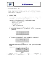
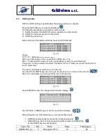
When the unit is switched on, the following display sequences will appear:
1. The backlighting will switch on and the following words will appear on the handheld
terminal display:
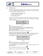
2. The display then shows the following, where x.xxx stands for the firmware version:
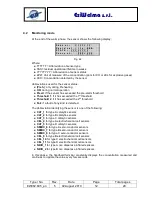
In this phase, the sensors begin the warm-up phase and the operation can take a few
minutes.
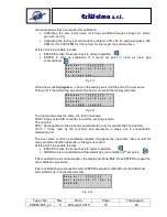
The display shows the following during the warm-up phase:
* * * * * * * *
Fig. 4.1
* * E S I W E L M A * *
U R 2 0 v e r s x . x x x
Fig. 4.2
S e n s o r :
T T T T T T T
R e s i d u a l l i f e : S S S
S T A T E : ( P r e h . )
C o n c e n t . : Z Z Z = X X X
Fig. 4.3


