Type / No.
Rev.
Date
Page
Total pages
EW082.695_en
5
02 August 2010
21
28
EsiWelma
s.r.l.
4.8
Troubleshooting
Cabling errors may show up as follows.
PROBLEM
POSSIBLE CAUSE
REMEDY
All the LEDs on units
concerned are off
Inversion of power supply on
peripheral units
Restore correct connection after
switching off the detector
Components broken, peripheral
units off
Power supply connections
inverted with 4...20mA output
connections
Replace damaged unit
Lack of communication
between sensor and TUS40-20
terminal unit
Positioning of the TUS40-20
junction card inverted or
misaligned
Restore correct BUS connection
after powering off the sensor
Table 4.1 – Diagnosis of possible causes of fail
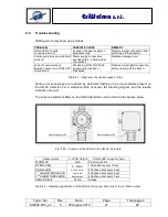
Some error sequences are reported by particular flashing in the visual alarms present on
the UR.20. detector. For a complete table of sensor fail reporting signals, see the relative
instruction manual.
The luminous alarms (LEDs) on the UR.20 detectors can be found in the figures below.
Fig. 4.25 – Function of the LEDs on the UR.20.. detectors
Sensor status
4...20mA Output
Status LED on sensor body
WARM-UP
2mA
Flashing at 2 Hz
OPERATING
4...20mA
0,10,20mA for
threshold
applications
1 flash about every 10 sec.
PRE-ALARM
2 flashes about every 5 sec.
1
st
ALARM THRESHOLD
3 flashes about every 5 sec.
2
nd
ALARM THRESHOLD
4 flashes about every 5 sec.
SENSOR FAIL
22mA
Steady
Table 4.2 – Operating significance of the LED on the sensor body and of the 4...20mA output
Operating status LED
Operating status LED


