Type / No.
Rev.
Date
Page
Total pages
EW082.695_en
5
02 August 2010
8
28
EsiWelma
s.r.l.
3
INSTALLATION
3.1
Installation of the TUS40-20 Terminal Unit
The TUS40 handheld terminal is constructed in plastic housing and it plugs into the junction
box via the coiled cable to be powered by the UR.20.. sensor.
A fold-out bar on the back of the TUS40 handheld terminal can be used to place it at a
convenient tilt on a minimum surface area of 220x130 mm. Knurling at the sides of the
keypad ensures an easy and secure grip.
The TUS40-20 terminal unit must be connected with the sensor power off; follow product
and/or installation instructions before opening the sensor cover. Proceed as follows to
connect the TUS40-20 terminal unit:
1. Make sure the area is clear of gas and that the sensor is not powered up
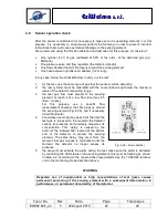
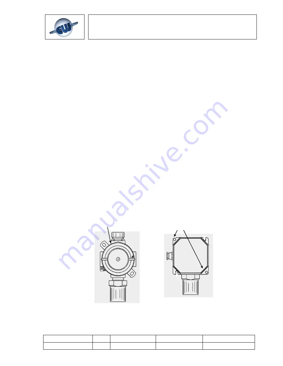
2. Open the UR.20 sensor cover (Fig.3.1)
3. Identify the position of the CN4 connector on the diagram (Fig. 3.2)
4. Plug the junction card into the socket, making sure it is properly lined up with the
contacts (Fig. 3.3), then plug the cable and handheld terminal into the junction card
RJ45 connector.
5. Power up the sensor
6. Wait for the handheld terminal display to switch on; it will show a row of asterisks,
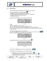
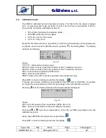
followed by the sensor status page (Fig. 4.1 and 4.2)
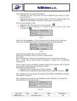
7. Wait for the end of the warm-up phase (preheating, Fig. 4.3)
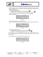
8. The handheld terminal will then show the basic display (Monitoring Mode).
It is now possible to operate with the handheld terminal (Fig. 4.4).
The direction of the detector must always have the sensor facing downwards
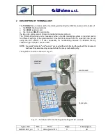
Fig. 3.1 – Removing the cover of the UR20 sensors
Turn the screw cover
anticlockwise
Remove the fastening
screws of the cover


