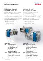
Elektronische Ölspiegelregulatoren
Electronic Oil Level Regulators
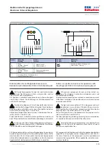
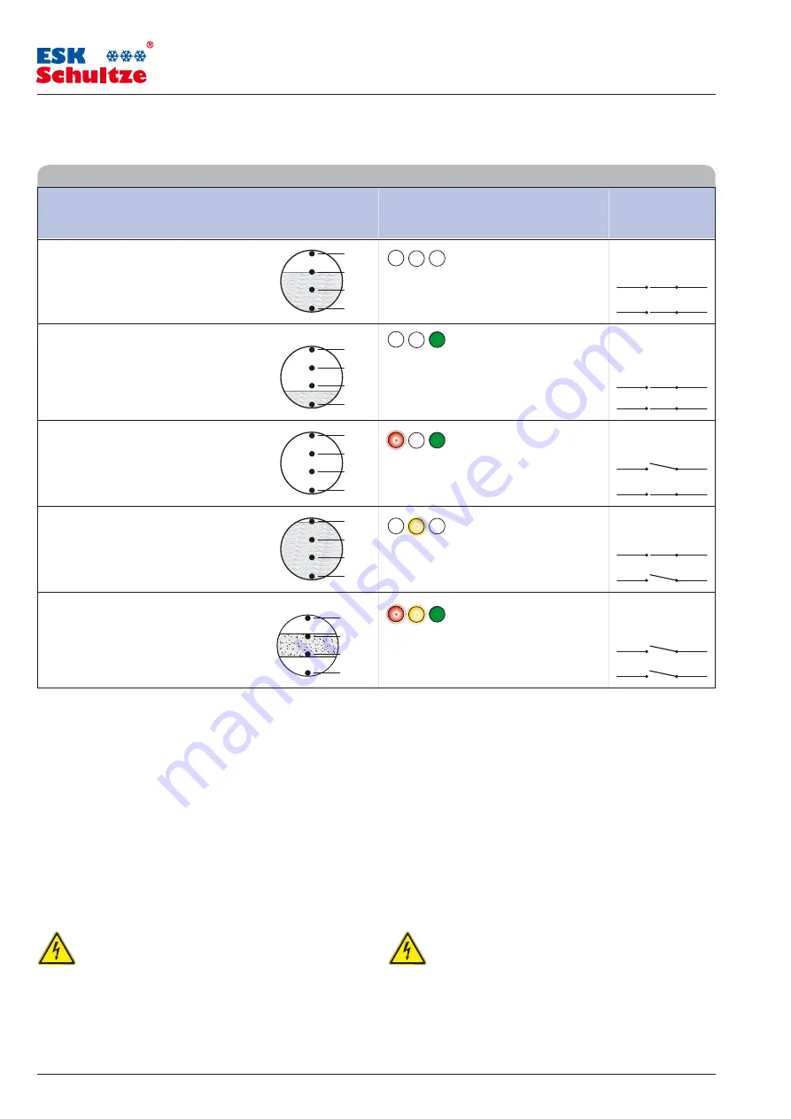
Nr.: Betriebszustand
Füllstand im
LED-Lichtsignal
Kontakte
Prismenschauglas
(rot – gelb – grün)
No.: Working state
Oil level at the
LED light signal
Contacts
prism sight glass
(red – yellow – green)
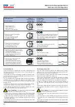
Funktionsbeschreibung
Operation Instruction
1. Gerät ist eingeschaltet
Ölstand Mitte Schauglas
Device switched on
liquid level is middle sight glass
2. Ölstand sinkt unter Mitte Schauglas
(Messpunkt MP3)
The oil level decreases beneath
the middle of the sight glass
(measuring point MP3)
3. Ölstand fällt trotz Füllvorgang weiter
bzw. Ölstand bei Start der Anlage
Oil level decreases in spite of
the refilling or starting oil level
4. Ölrückführung aus der Anlage erhöht bzw.
erhöhter Kurbelgehäuse-Füllstand aufgrund
von Kältemittelverlagerung
Increased oil return through the system
or higher crankcase oil level due to the
refrigerant displacement
5. Verunreinigung im Bereich MP 2 / MP 3
und Ölstand sinkt unter MP4 –
Notlaufbetrieb startet (siehe Erklärung)
Contamination in the area of MP 2 / MP 3
and the oil level decreases under MP4 –
emergency mode starts (See explanation)
Kein Lichtsignal
7 8
No light signal
9 10
Grüne LED leuchtet, Prozessor schaltet Magnetventil,
getakteter Füllvorgang (Füllen und Messen) beginnt
Green LED shines, processor opens the solenoid
7 8
valve. The pulsed oil refilling process (filling and
measuring) is started
9 10
Nach 2 Minuten Unterfüllung blinkt rote LED
7 8
Red LED starts blinking after
two minutes of underfilling
9 10
Gelbe LED beginnt zu blinken
7 8
Yellow LED starts blinking
9 10
Rote und gelbe LEDs blinken –
getakteter Füllvorgang beginnt
7 8
Red and yellow LEDs starts blinking –
The pulsed oil refilling process is started
9 10
.1
.1
.1
.1
.1
.1
.1
.1
.1
.1
.1
.1
.1
.1
.1
.1
.1
.1
.1
.1
Der Notlaufbetrieb
Durch verunreinigtes Öl (zum Beispiel nach einem Motorschaden oder
Wicklungsbrand am Verdichter) können sich am Prismenschauglas Ver-
schmutzungen absetzen.
Treten, bedingt durch die Verschmutzung, Störungen an einem oder meh-
reren Messpunkten auf, wird ein Notlaufbetrieb aktiviert, der die Ölversor-
gung des Verdichters übernimmt.
Dass sich der Regulator im Notbetrieb befindet, wird durch das gleichzei-
tige Blinken der roten und gelben LEDs signalisiert. Die Kontakte
7/8
und
9/10
sind dabei permanent geöffnet. Das Öffnen des Magnetventils zeigt
die grüne LED an.
Der Ölstand im Verdichter wird je nach Verschmutzungsgrad des Prismen-
schauglases zwischen den Messpunkten
MP3
und
MP4
gehalten.
Der Notlaufbetrieb gewährleistet einen minimalen Füllstand und verhin-
dert so bis zum Eintreffen des Service den Ölnotstand.
Alarm „Überfüllung“:
Es wird empfohlen, den Verdichter
nicht
mittels dieser Funktion abzuschalten, denn:
befindet sich der Verdichter im Stillstand und die Überfüllungsanzeige
leuchtet, kann dieser nicht gestartet werden. Ein Reset ist nicht möglich.
gelangt während des Betriebs zusätzlich Öl über die Saugseite in das
Kurbelwannengehäuse, so dass Überfüllung signalisiert wird, wird der
Verdichter abgeschaltet.
Das Signal kann verwendet werden, um weitere Informationen über den
Anlagenzustand zu bekommen.
The Emergency Operation
Dirt at the surface of the prism sight glass, for example caused by engine
damage or a burn out of the motor winding, maybe generate failure mal-
functions on one or more points of measurement.
In such conditions a emergency operation will be activated. This operating
mode ensures the oil supply of the compressor.
The emergency operating mode is signalized by simultaneously blinking
of the red and the yellow LEDs. The contacts
7/8
and
9/10
of the relays are
open. The opening of the solenoid valve is signalized by the green LED.
In subject to the degree of pollution the oil level inside the crankcase of
the compressor will be adjusted between the measuring points
MP3
and
MP4
.
The emergency operation mode warranted a minimum oil level and pre-
vents hazardous oil deficiency until the arrival of a refrigeration service
technician.
Alarm „High Level“:
It is recommended
not to use
this function
to switch off the compressor because:
the compressor can‘t start, if the high level alarm is activated. A reset is
not possible.
the compressor will switch off during working, if you have oil carry over
the suction line in the crankcase and the level increasing the high level
alarm.
The signal can be used to get further details about the operating condition
of the refrigerating plant.
6/8
씮

