6
INSTALLATION (CONTINUED)
TABLE1
MODEL
C
D
DVEL 8N - DVEL 8L
19 ½” (495 mm)
6 ¾” (172 mm)
DVEL 12N - DVEL 12L
19 ½” (495 mm)
7 ¾” (197 mm)
DVEL 20N - DVEL 20L
19” (483 mm)
8 ¾” (222 mm)
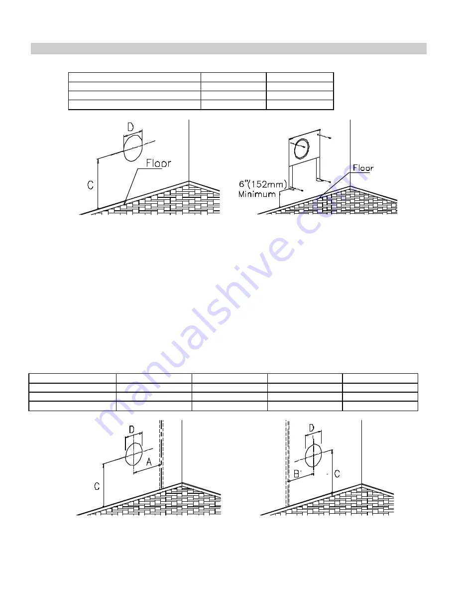
Figure 5 Figure 6
2. Drill through the wall according to measurements and positions indicated.
3. Place hanging bracket over the hole. After leveling the hanging bracket, mark the four holes as shown in figure 6.
4. Remove the hanging bracket and drill the four holes.
5. Insert in each hole the anchors provided.
6. Place back the hanging bracket and fix it with four screws.
INSTALLING THE HANGING BRACKET ON A WOODEN WALL
1. Taking into account the minimum clearances mentioned in figure 4, locate the closest wall stud (which will serve to
hold the appliance) and mark the hole center at a distance “A”, (if wall stud is at the right), or “B”, (if the stud is at
the left). See table 2 and figures 7 and 8.
2. Draw the position of the hole for the vent-air intake pipe. See diameter of the hole “D” and height to the center “C”
in table 2 for the different models. Height “C” is the minimum recommended.
TABLE 2
MODEL
A
B
C
D
DVEL 8N - DVEL 8L
5 9/16” (141 mm)
3 31/32” (101 mm)
19 ½” (495 mm)
6 ¾” (172 mm)
DVEL 12N - DVEL 12L
7 13/16” (198 mm)
5 7/16” (138 mm)
19 ½” (495 mm)
7 ¾” (197 mm)
DVEL 20N - DVEL 20L
13 11/64” (335 mm)
10 7/8” (276 mm)
19” (483 mm)
8 ¾” (222 mm)
Figure 7 Figure 8
Summary of Contents for DVEL 12
Page 13: ...12 OPERATION CONTINUED Pilot Burner...
Page 14: ...13 POUR COUPER L ADMISION DE GAZ DE L APPAREIL Veilleuse ALLUMAGE...
Page 20: ...19 Model DVEL 8 19...
Page 21: ...Model DVEL 12 20...
Page 22: ...Model DVEL 20 21...


