Model D50 service manual, SMD50l-ac Page 5
eskridge, inc. olathe, KS. 913-782-1238 www.eskridgeinc.com
unit Disassembly Procedure
There are two types of model D50 units: single planetaries with-
out a primary carrier and double planetaries with a primary planet
carrier. The differences in disassembling single stage and double
stage gearboxs are clearly defined throughout this manual.
All parts should be inspected as they are removed from unit.
1)
Scribe across base
(1)
, ring gear
(8)
and cover/ bail assembly
(3)
joints on outside of gearbox to assure proper orientation
of oil fill and drain plugs, motor mounting, etc., as the unit is
reassembled.
2)
Remove hydraulic motor
(15)
from auger drive. Drain oil.
3)
Remove the twelve 7/16 x 4-1/2” socket head cap screws
(12a)
and 7/16 lockwashers
(12b)
, which retain cover/bail
assembly
(3)
and ring gear
(8)
to base
(1)
.
4)
Lift cover / bail assembly
(3)
off of unit.
Single stage: Remove input gear
(4)
, input thrust washer
(7a, 7b)
carrier assembly
(7)
and ring gear
(8)
.
Double Stage:Remove input gear
(4)
, input thrust washer
(9a)
primary carrier assembly
(5).
Remove
secondary sun
(6)
thrust washer
(9b)
and
secondary carrier
(7)
.
5)
The gearing is now disassembled and area(s) requiring re-
pair or service should be identified by thorough inspection
of the parts after they have been washed in solvent. Rotate
planet gears to check for any abnormal noises or roughness
in the primary planet bearings. At the same time, inspect
planet gears for any damage or worn teeth. Replace carrier
assembly if any problems are found in the carrier assembly.
base Subassembly
Disassembly
1)
Place unit on a press table with the output shaft
(2)
protruding
downward through a hole in the table; unit should be support-
ed only by the base
(1)
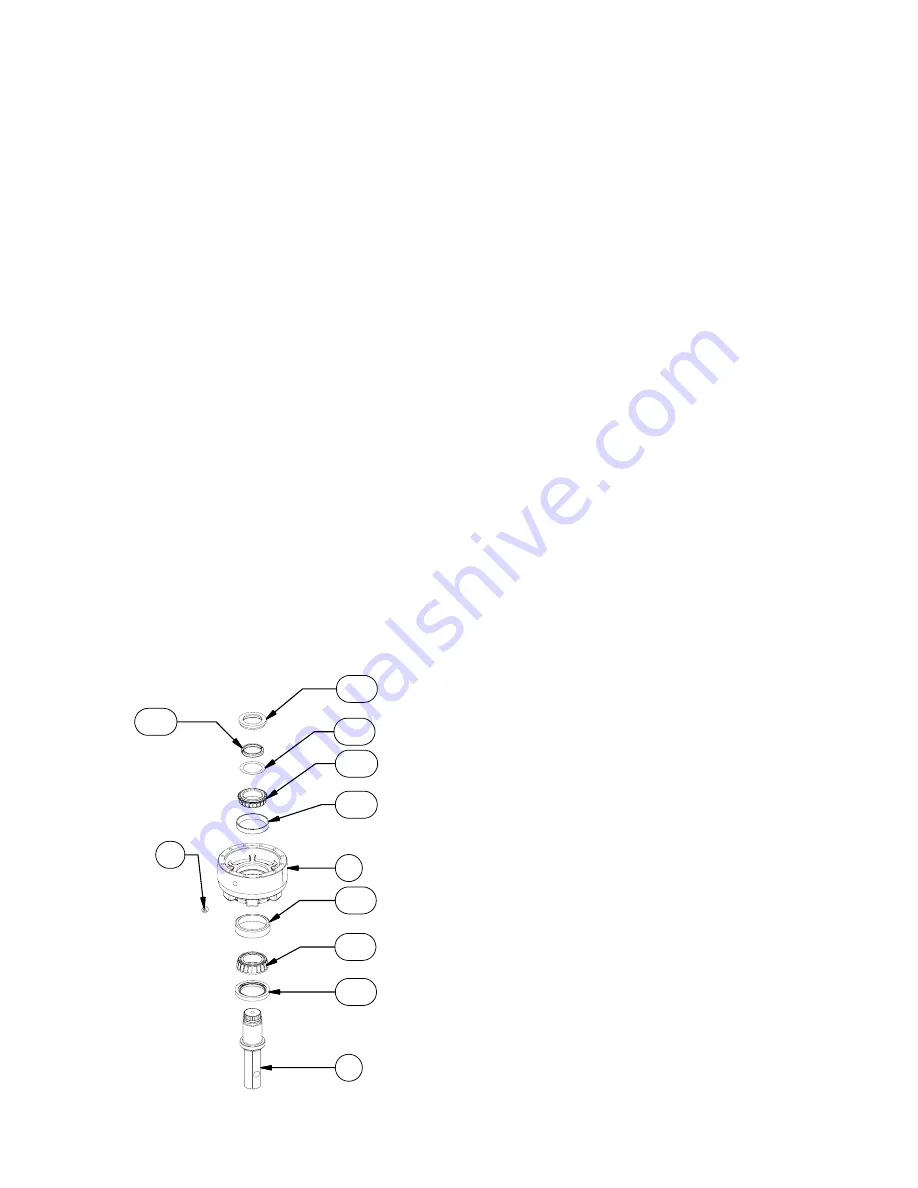
. The only thing retaining output shaft
(2)
is the locking ring
(14b)
and split ring segments
(14c)
.
Remove the locking ring
(14b)
by prying upward, split ring
segments
(14c)
and shims
(14a).
cauTion: The load-n-lock assembly is no longer retaining
output shaft. Take precautions if the unit is moved as the shaft
may fall out.
2)
With output shaft down through centerhole in press table and
unit supported by base, press shaft out by applying press
load to top end of shaft
(internal end)
until it passes through
inner shaft bearing
(11c)
. Outer shaft bearing
(11a)
and seal
(10b)
will come out of unit attached to shaft.
3) Inspect inner and outer bearing cups
(11b & 11D)
. If cups are
damaged remove and replace both bearing cups and cones.
cauTion: care should be taken not to injure feet or damage
output shaft during this procedure.
4)
If outer bearing cone
(11a)
needs to be replaced, it will need
to be pressed off of output shaft. Also inspect inner bearing
cone
(11c)
. If any one bearing component needs replaced
replace the both the cup and cone as a set.
noTe: When installing or removing bearings, press only on
inner race of bearing cone. Do noT press on outer roller cage
of bearing or it will damage bearing.
5)
Clean all foreign material from magnetic oil plug
(13)
located
on bottom of base
(1)
. Add a small amount of pipe thread
compound to pipe plug before installing it back into base.
unit reassembly
1)
Start with base
(1)
. Turn base upside down and position
on press table. Base should be pointing upward with outer
bearing cup
(11b)
exposed. Apply a layer of lithium bearing
grease to bearing cup surface.
2)
Invert output shaft
(2, load-n-lock retainer groove end
down)
and carefully lower into base
(1)
until the shaft’s out-
er bearing cone
(11a)
is seated against outer bearing cup
(11b)
.
3)
Press shaft seal
(10b)
into base until it is flush with bottom of
pilot diameter. Use a press fixture, if possible, to avoid distort-
ing seal. If press fixture is not available, a hammer and flat-
ended drift may be used by tapping outer edge of seal lightly
and alternating sides.
4)
Stand base assembly upright on output shaft.
cauTion: The only thing holding output shaft and base to-
gether at this point is the tightness in fit of the shaft seal. Se-
curely and cautiously turn unit upright, not allowing base and
shaft to separate.
5)
While holding output shaft
(2)
with one hand, rotate base
(1)
to be certain it turns freely and smoothly. The slight resistance
felt, if any, is due to shaft seal load (drag) on output shaft.
6)
Apply a layer of lithium bearing grease to inner bearing cup
(11D)
surface.
7)
Install inner bearing cone
(11c, small end down)
over inter-
1
2
10B
11A
11B
11C
11D
14A
14B
14C
13


