44
Einstellen der Helikopter-Elektronik
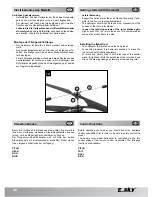
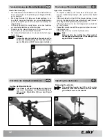
Lösen Sie das Anlenkgestänge für die Fliehgewichtstange
vom Rotorkopf, indem Sie das Gestänge vorsichtig von dem
Kugelkopf hebeln.
Biegen Sie die Kunststoffhalterung der Fliehgewichtstange
auf der Rotorwelle leicht auseinander und
nehmen Sie die Fliehgewichtstange ab.
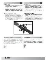
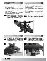
Lösen Sie jeweils eine Schraube der Rotorblatthalterung und
entnehmen Sie die Rotorblätter.
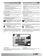
Der Rumpf ist mit zwei quer durch den Rumpf geführten Stiften
am Chassis befestigt (25).
Der eine Stift geht auf halber Höhe mittig durch Rumpf und
Einbauten, der zweite Stift hält den Rumpf oben hinter dem
Rotorkopf am Chassis.
Entfernen Sie jeweils einen der beiden Gummistopfen von
dem Haltestift und
ziehen Sie diesen dann von der anderen Seite heraus.
Die blaue LED am Heckausleger (Positionslicht) ist noch mit
dem Elektronik-Baustein verbunden.
Ziehen Sie den Stecker des Anschlusskabels rechts unten
aus dem Elektronik-Baustein
Das Chassis mit der gesamten Bordelektronik
lässt sich jetzt von unten aus dem Rumpf ent-
nehmen (6).
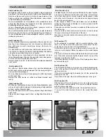
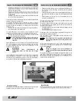
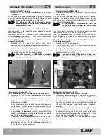
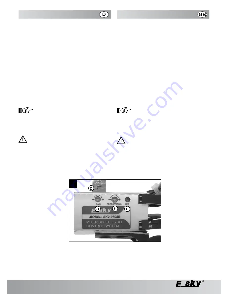
Auf dem Elektronik-Baustein (27) befinden sich zwei Einstellregler
(a, b), mit deren Hilfe Sie das Flug- und Steuerverhalten Ihres
Modellhelikopters bei Bedarf anpassen können.
ACHTUNG!:
Trennen Sie den Flugakku vom Helikopter, bevor
Sie Änderungen vornehmen.
Der Regler ist ab Werk bereits voreingestellt, sodass Sie im
Regelfall keine Veränderungen vornehmen müssen. Sollten Sie
jedoch mit dem Flug- und Steuerverhalten Ihres Modellhelikopters
unzufrieden sein, können Sie folgende Änderungen vorneh-
men:
Heck-Funktion
Sollte die Trimmung der Heckfunktion nicht ausreichen, so
haben Sie die Möglichkeit mit dem Einstellregler (b) eine zusätz-
liche Trimmung vorzunehmen.
-
-
-
-
-
-
-
Adjusting the electronics
Detach the linkage rod for the centrifugal weight rod from
the rotor head by carefully prying the rod assembly from the
spherical head.
Bend slightly apart the plastic retainer for the centrifugal
weight rod on the rotor shaft and take off the centrifugal
weight rod.
Unscrew one screw each for the rotor blade retainer and take
off the rotor blades.
The fuselage is attached to the chassis by two pins that run
through the fuselage crosswise (25).
One of the pins goes midway through the fuselage and avionics,
and the second pin holds the fuselage to the chassis at the top
behind the rotor head.
Remove one of the two rubber stoppers from the retainer pin
in each case and
then pull it out from the other side.
The blue LED on the tail boom (navigation light) is still attached
to the electronics module.
Pull the plug of the connecting cable out of the electronics
module on the bottom right-hand side.
The chassis along with the entire avionics can
then be taken out of the bottom of the fuselage
(6).
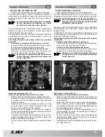
There are two adjusters (a, b) on the electronics module (27)
with which you can, if necessary, adjust the flying and steering
behaviour of your model helicopter.
ATTENTION!
Disconnect the flight battery from the helicopter
before making any changes.
The adjuster is pre-set ex factory, and in general, you should not
carry out any modification. However, if you are not satisfied with
the flying and steering behaviour of your model helicopter, you
can carry out the following modifications:
Tail Function
If the steering trimm for tail function is not enough, you can trim
the tail function additionally with adjuster (b).
-
-
-
-
-
-
7

