User Manual
Doc. Number: ESO-323064
Doc. Version: 2
Released on:
Page:
22 of 82
Document Classification: Public
The scanning lens of the field selector is mounted on an XYZ table: the XY axes enable the
star used for AO correction to be selected in the 22.8
’’x
33.8
’’
field-of-view, while the Z stage
compensates for the VLT field curvature. The position of the field selector defines the
reference for the pointing. The imaging lens creates an image of the AO star on the
membrane mirror, which is mounted on an acoustic cavity. A voice coil is mounted to the
other end of the cavity and driven at 2.1kHz by the APD counter module to force an
oscillation of the focus mode of the membrane mirror. The incidence angle of the beam on
the membrane mirror depends on the position of the guiding star in the field. In order to
keep the pupil image (obtained when the membrane mirror is flat) centred on the lenslet
array, the membrane mirror is mounted on a 2-axis gimbal mount, which is coordinated with
the field selector. For each (x, y) position of the field selector the gimbal mount is moved so
that the light is reflected to the same focus. A diaphragm in front of the membrane enables
the field to be adjusted to the observing conditions (seeing and guiding reference size). The
assembly of the gimbal mount is shown in Figure 12.
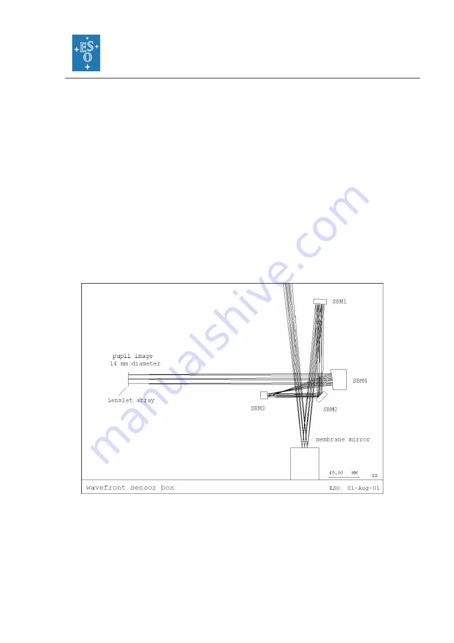
The wavefront sensor box consists of 4 mirrors, which provide parallel beam to image the
pupil on the lenslet array. First, the beam is collimated by a spherical mirror. It is then folded
by a flat mirror and injected in the beam expander, which adapts its diameter to the lenslet
array (14 mm). The optical path of the wavefront sensor box is shown in Figure 13.
Figure 13: The optical path of the wavefront sensor box.
The lenslet array intercepts the beam and divides the flux in 60 sub-apertures. Each sub-
pupil is imaged on a fiber, with a 100 μm core diameter. When the membrane mirror
vibrates, the pupil image is projected on both sides of the lenslet array plane. The
normalized difference between the intra- and extra-pupil flux collected by each sub
–
aperture is proportional to the local wavefront curvature, which provides the wavefront error.
The fibers drive the signal from the fiber feed module to the APD cabinet, mounted on the


