Page 16
06-Mar-1997
VME4ST Backplane technical manual
Doc. VLT-MAN-ESO-17130-0992
4.1.7 FC0-FC2
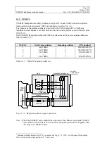
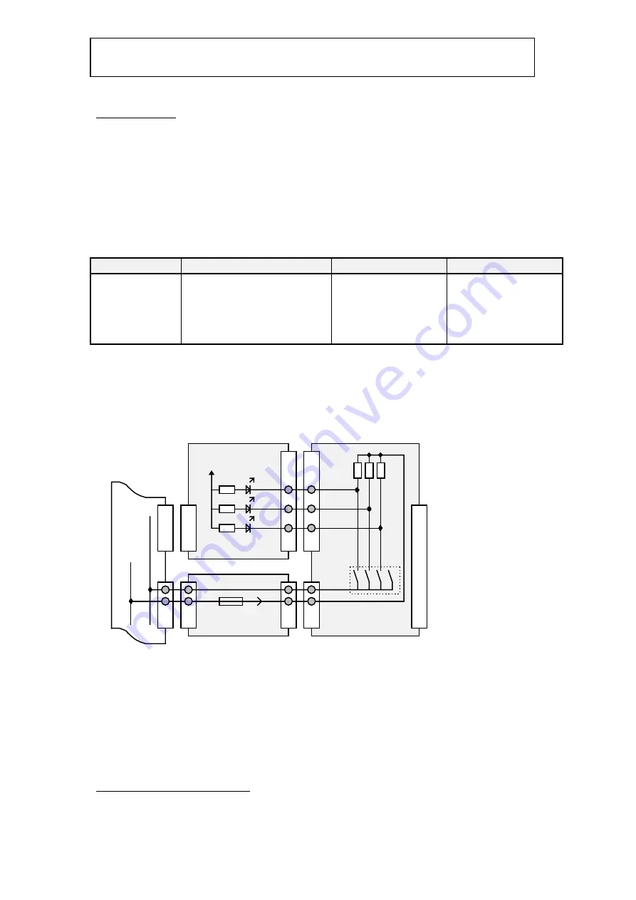
VME4ST Backplane Assembly Address setting bit 0-2. Input to MAC4 motion controller
from position code switch array SW1 on backplane. See also Fig. 3.2.
The purpose of the address coding is to provide to the VME master CPU a VME-slot
identification mechanism if several sub-sets of motion control systems exist within the same
VME LCU.
Each VME4ST backplane within one VME-bus chassis must be given a unique address as
listed in table 4.1.7 :
MAC4 #
MAC4 base address
Backplane address
SW1 position
1
0xC10000
1
ON-OFF-OFF-X
2
0xC20000
2
OFF-ON-OFF-X
3
0xC30000
3
ON-ON-OFF-X
:
:
:
:
7
0xC70000
7
ON-ON-ON-X
Table 4.1.7. VME4ST backplane addresses.
MAC4
VME4ST
VME4ST P2 BACKPLANE
MOTOR
CONNECTOR
(ONE AXIS)
VME
BUS
FC2
OPTO-
COUPLERS
FC1
FC0
G
N
D
SW1
1
2
3
4
V
C
C
FUSE 1.5A
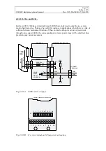
Fig 4.1.7.1. Backplane address signal connection.
Note :
When the VME4ST servo amplifier is not present, the address code inputs FC0-FC2
of the MAC4 unit will all be low (0) because the pull-up resistors are supplied with
+5V from the VME4ST board.
1
Indication of individual switch 1,2,3,4 position. See fig 4.1.7.2. OFF = switch open (left position),
ON = switch closed (right position), X = don’t care.


