Page 30
06-Mar-1997
VME4ST Backplane technical manual
Doc. VLT-MAN-ESO-17130-0992
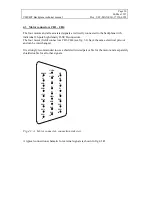
4.3 Motor connectors CH1 - CH4
The four motors and all associated signals are directly connected to the backplane with
individual 26-pole high density D-SUB connectors.
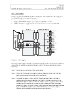
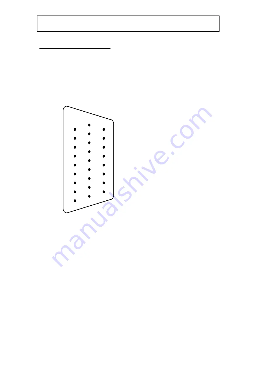
The four motor (field) connectors CH1-CH4 (see fig. 3.1) have the same electrical pin-out
and can be interchanged.
It is strongly recommended to use a shielded twisted pair cable for the motor and a separately
shielded cable for all other signals.
/HOME
LL
PHB-
PHB+
+5VA
PH4-
PH4+
PH1-
PH1+
GNDA
GNDA
A-
A+
MSH
PH5+
PH2-
PH2+
UL
SP2
SP1
Z-
Z+
VX
PH5-
PH3-
PH3+
1
9
10
18
26
19
Fig. 4.3.A. Motor connector, connection side view.
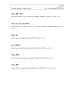
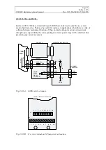
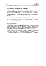
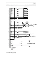
A typical connection schematic for external signals is shown in fig 4.3.B.

