background image

8

Step 4: Set the Date and Time

This will allow the security video taken by AlertCam to display
the correct date and time it was taken.

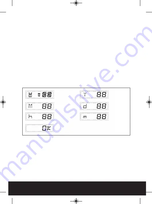
Push TIME/DATE SET button (see Fig. 10) for 3 seconds, the LCD
screen will then flash 3 times, indicating you have entered
Time/Date setting mode. 

1. “YEAR”setting: ”Y” and “08” are displayed on the screen; push the

button to set year from “08-99”, push the button again and hold
for 3 seconds to scroll through numbers quickly.  If you have not
pressed the button for 3 seconds, it will automatically save the
year and go on to allow you to set the month.

2. Repeat the same setting procedure for

MONTH/DATE/HOUR/MINUTE.

Important note:

In the event of a power failure of less than 50 hours Alertcam
has on board power storage to maintain time and date settings.
Should the power be switched off for more than 50 hours its is
essential to reset the time and date to maintain correct operation
of the unit.

1. START

3. MONTH

Setting

2. YEAR

Setting

4. DATE

Setting

6. MINUTE

Setting

5. HOUR

Setting

FINISH

Fig. 10

AlertCam Manual_Layout 5  28/02/2013  16:57  Page 8

Summary of Contents for AlertCam

Page 1: ...Standalone combined PIR camera with RF transmitter AlertCam Manual_Layout 5 28 02 2013 16 57 Page 1 ...

Page 2: ...RE ATTEMPTING ANY INSTALLATION OR MAINTENANCE ENSURE THAT THE ELECTRICAL SUPPLY IS SWITCHED OFF AND THE CIRCUIT FUSES REMOVED OR THE CIRCUIT BREAKER IS IN THE OFF POSITION Please make sure the voltage and polarity are correct before connection Incorrect voltage may cause electric shock If you are not sure please contact your distributor Table of contents Contents and Optional Extras 3 Step 1 Insta...

Page 3: ...vers Disk 1 x Allen key 2 x screws 2 x masonry plugs USB Cable 2G SD card Contents Optional Extras AlertCam RA Remote chime alarm device AlertCam RS Remote 1500w switching device AlertCam Manual_Layout 5 28 02 2013 16 57 Page 3 ...

Page 4: ...Feed the required cables through the glands supplied 3 If AlertCam is to be used without a local lighting unit please see wiring diagram Fig 2 4 If AlertCam is to be used to switch a local light unit max 500w please see wiring diagram Fig 3 5 Ensure all wires are connected securely and that no loose strands are exposed Make sure the polarity is correct Double check the connections after wiring Err...

Page 5: ...press OFF button and take it out within 30 seconds When LED light turns green SD card is being read do not remove SD card at this time or data may be lost To remove SD card push in SD card to eject BROWN LIVE IN NEUTRAL RED SWITCHED LIVE Fig 2 Fig 3 Important note Please remove the plastic lens cover from camera after installation Fig 5 Fig 4 AlertCam Manual_Layout 5 28 02 2013 16 57 Page 5 ...

Page 6: ...at either side of the AlertCam 2 The laser spot is the center position of the camera angle position Time control Turn the time control knob to side to increase the illumination time 7 minutes max turn the control knob to side to reduce the illumination time 30 seconds min Lux control The lux control is used to set the required ambient light required to activate the light switching capability of Al...

Page 7: ...ress this button in case of system malfunction Off Rec Please press Off Rec button to remove SD card Please remove card within 30 seconds of pressing the Off Rec button to avoid loss of data RF Switch Code The AlertCam has a built in RF transmitter approx 60m open field range that can send wireless trigger signals to the optional AlertCam RA remote alarm unit or AlertCam RS remote switching unit T...

Page 8: ...mbers quickly If you have not pressed the button for 3 seconds it will automatically save the year and go on to allow you to set the month 2 Repeat the same setting procedure for MONTH DATE HOUR MINUTE Important note In the event of a power failure of less than 50 hours Alertcam has on board power storage to maintain time and date settings Should the power be switched off for more than 50 hours it...

Page 9: ...d USB Port 2 5GB free hard disk space Installing the viewing drivers Insert the provided CD ROM Locate the files on your PC Chose IP298X USB CAMERA Follow the instructions on the installation screens If you computer doesn t run the installation program automatically please click the Start button and choose Run Then browse your computer to find the file name under which you saved the driver and cli...

Page 10: ...m the slot Put the SD card part no 2 into a card reader connect PC and card reader and open SDR View Click m button to choose which recording file you want to see the video then click f or g button to forward or backward playing the video Fig 12 Viewing direct live video during installation It is possible to view live images directly from the AlertCam to a laptop during installation to ensure the ...

Page 11: ...Technical Specification PIR detection range 10m PIR detection angle 160 Deg adjustable Camera viewing angle 60 deg Camera resolution 640x480 Max direct load 500W 50W LED Camera controls Automatic white balance and exposure Recording medium SD FAT16 or SDHC FAT32 Max 32GB Record rate 2 FPS for 20secs per trigger Recording capacity with supplied 2GB SD 1 000 files of 40 images Image format JPEG conv...

Page 12: ...r viewing captured images each time any of the following events occur After a mains power removal from the AlertCam After removing the SD card for viewing prior to replacing in the AlertCam To format the SD card Please ensure to save any required images to an alternative folder prior to formatting Place it in the SD USB adaptor supplied Place the adaptor in a spare USB port on your PC Laptop Right...

Reviews: